
Installation Manual
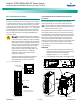

NetSure
™
9500 120kW 400V DC Power System
Installation Manual, IM584001200 (Issue AA, April 14, 2014)
Spec. No: 584001200 Code: IM584001200
Model No: 9500 Issue AA, April 14, 2014
[17 of 25]
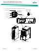
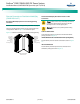
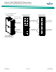
Electrical Connections to Battery Cabinet
(584001200 List 90, 91, 92, 93)
Danger! Adhere to the “Important Safety Instructions”
presented at the front of this document. DO NOT
attempt to work on an energized system.
Warning! Check for correct polarity before making
battery connections.
Note:
The maximum short circuit capacity of the circuit breakers in
the system is 25kAIC. Therefore, the maximum number of
Emerson provided Battery Cabinets is limited to a maximum of
three (3). The use of a fourth Battery Cabinet will exceed the
short circuit rating of the circuit breakers in the system.
Batteries are factory installed and connected in the Battery
Cabinet.
Note:
Batteries are physically factory installed, but require one series
strap connection to complete the string wiring. The batteries
as shipped are connected with one wire disconnected in the
middle of the string, for shipping safety.
The Battery Cabinet is furnished with separate installation
instructions (IM58400120090). Refer to these instructions to
make the follow connections to the Battery Cabinet.
• Battery Cabinet Frame Grounding/Earthing Connection
(see also “General Grounding/Earthing Guidelines” on
page 4)
• 48V Battery Breaker Shunt Trip Connection (see also
“Power Module/Bay Battery Breaker Alarm/Shunt Trip
Connections” on page 12)
• Battery Breaker Alarm Connections (see also “Power
Module/Bay Battery Breaker Alarm/Shunt Trip
Connections” on page 12)
• Battery Connections to the Power Module/Bay (see also
“Power Module/Bay Battery Connections” on page 12)
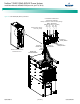
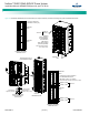
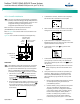
Installing the Rectifier Module
The rectifier module is hot swappable. It can be installed with the
system operating if these instructions are carefully followed.
Note:
There is a two-step insertion process.
PROCEDURE
1. Unpack the rectifier module.
2. If present, remove the blank cover panel from the
rectifier module mounting position.
3. Open the respective rectifier module’s AC input circuit
breaker on the front of the power and control section of
the Power Module/Bay. Refer to Figure 17 for circuit
breaker location.
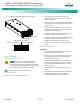
4. Place the “Latch Release” located on the front of the
rectifier module to the LEFT position. See Figure 16.
5. Place the rectifier module into an unoccupied mounting
slot without sliding it in completely. Gently push the
rectifier module into the mounting slot until it stops.
Note that the rectifier module will NOT be completely
seated in the mounting slot until the next step is
performed.
6. Live Systems: Wait for the green power indicator to
illuminate. Ensuring the green power indicator stays on,
slide the “Latch Release” located on the front of the
rectifier module to the RIGHT position. Gently push the
rectifier module into the mounting slot until it is
completely seated.
De-energized Systems: Slide the “Latch Release” located
on the front of the rectifier module to the RIGHT position.
Gently push the rectifier module into the mounting slot
until it is completely seated.
7. Secure the rectifier module to the power and control
section of the Power Module/Bay by tightening the
retaining screw.
8. Repeat the above steps for each rectifier module being
installed in the system.
9. After the rectifier modules are physically installed in their
mounting slots, they are ready for operation immediately
after power is supplied to them.
10. Close the respective rectifier module’s AC input circuit
breaker on the front of the power and control section of
the Power Module/Bay.
D
a
n
g
e
r
W
a
rn
in
g