
Installation Manual

NetSure
™
9500 120kW 400V DC Power System
Installation Manual, IM584001200 (Issue AA, April 14, 2014)
Spec. No: 584001200 Code: IM584001200
Model No: 9500 Issue AA, April 14, 2014
[12 of 25]
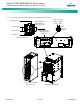
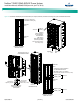
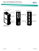
Power Module/Bay Battery Breaker Alarm/Shunt Trip
Connections
For Emerson provided Battery Cabinet, a battery breaker
alarm/shunt trip cable (P/N 557867) is provided with the system.
This cable connects between the power and control section of the
Power Module/Bay (see Figure 12) and the Battery Cabinet (see
Battery Cabinet instructions IM58400120090).
Customer battery solutions must utilize a compatible battery
breaker. Also one (1) Battery Breaker Alarm/Shunt Trip cable (P/N
557867) must be ordered for each battery string. Battery breaker
requirements are as follows.
• Battery breaker must contain a 48V shunt trip with the
following specifications.
a. Rated Voltage: 48 to 60 VDC.
b. Maximum Release Duration: 15ms.
c. Minimum Resistance: >15 ohm.
• Battery breaker must contain auxiliary contacts that are
normally closed if the breaker is closed. Minimum
contact rating is 48V DC at 2A.
• It is recommended that the battery breaker have a lock-
out/tag-out feature to allow for maintenance safety.
Power Module/Bay Battery Shunt Connections
The battery shunt connectors on the power and control section of
the Power Module/Bay are factory connected to the battery shunts
also located in the Power Module/Bay. See Figure 12.
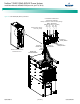
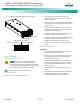
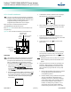
Power Module/Bay Battery Connections
Danger! Adhere to the “Important Safety Instructions”
presented at the front of this document. DO NOT
attempt to work on an energized system.
Warning! Observe proper polarity when making battery
connections.
Note:
The maximum short circuit capacity of the circuit breakers in
the system is 25kAIC. Therefore, the maximum number of
Emerson provided Battery Cabinets is limited to a maximum of
three (3). The use of a fourth Battery Cabinet will exceed the
short circuit rating of the circuit breakers in the system.
Note:
The short circuit current generated by a customer provided
battery option cannot exceed 25kAIC.
Up to four battery strings can be connected to the battery
terminals located in the Power Module/Bay. Connect the battery
strings to the positive and negative battery connection points per
Figure 13. Refer to SAG584001200 for wire size and crimp lug
information. See separate Battery Cabinet instructions
(IM58400120090) for connection points in the Battery Cabinet.
Wa
rn
i
ng
D
a
n
g
e
r