
Installation Manual
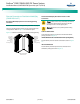

NetSure
™
9500 120kW 400V DC Power System
Installation Manual, IM584001200 (Issue AA, April 14, 2014)
Spec. No: 584001200 Code: IM584001200
Model No: 9500 Issue AA, April 14, 2014
[11 of 25]
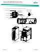
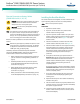
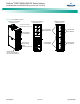
ACU+ Controller Ethernet Connection
The ACU+ controller provides a Web interface via an Ethernet
connection. This interface can be accessed locally on a computer
or remotely through a network. An RJ-45 10BaseT jack is provided
on the front of the ACU+ controller for connection to a computer
or into a customer's network. This jack has a standard Ethernet pin
configuration scheme, twisted pair. Refer to Figure 10 for location.
Use shielded Ethernet cable (grounded at both ends). Note that
the ACU+ RJ-45 jack is connected to chassis ground. Refer to the
ACU+ Controller Operation Instructions (UM1M820NNB-2) for
operational details.
Warning! The intra-building port(s) of the equipment or
subassembly is suitable for connection to intra-building
or unexposed wiring or cabling only. The intra-building
port(s) of the equipment or subassembly MUST NOT be
metallically connected to the interfaces that connect to
the OSP or its wiring. These interfaces are designed for
use as intra-building interfaces only (Type 2 or Type 4
ports as described in GR-1089-CORE, Issue 4) and
require isolation from the exposed OSP cabling. The
addition of Primary Protectors is not sufficient
protection in order to connect these interfaces
metallically to OSP wiring.
The intra-building port (RJ-45) of the equipment or
subassembly must use shielded intra-building
cabling/wiring that is grounded at both ends.
Figure 10. ACU+ Ethernet Port
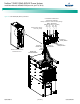
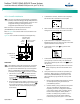
Power Module/Bay External EPO (Emergency Power Off)
Connections
The Power Module/Bay has an Emergency Power Off (EPO)
function operated by a remote contact provided by the User.
Note:
The external EPO switch wiring must be double-insulated. The
wire must be 600V, 18-16 AWG stranded for maximum runs
between 82 and 197 feet (25-60m).
When the EPO switch is momentarily closed, the main AC input
circuit breaker located on the power and control section of the
Power Module/Bay and the battery disconnect circuit breakers (if
connected to the BATT1 CTRL, BATT2 CTRL, BATT3 CTRL, and/or
BATT4 CTRL connectors located on the rear of the power and
control section of the Power Module/Bay) are tripped open to
isolate the system from all electrical sources. Manual intervention
is required to restart the system. Restart the system by first
turning ON the main AC input circuit breaker then the battery
circuit breaker(s).
PROCEDURE
1. Connect a customer provided external normally open
switch between the EPO terminals provided on the rear
of the power and control section of the Power
Module/Bay. Refer to Figure 11 for location.
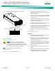
Figure 11. Power Module/Bay EPO (Emergency Power Off) Terminals
ACU+ Controller
ESC EN T
10/100M Ethernet
Port (RJ-45)
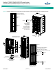
120kW Power Module/Bay
584001200 List 01
Power and
Control Section
ACU+ Controller
Front door removed in
illustration for clarity only.
Rear
Rear
Power and Control Section
BATT1
CTRL
BATT2
CTRL
BATT3
CTRL
BATT4
CTRL
AC INPUT
CTRL
CAN
BATT SHUNT 4
BATT SHUNT 3
BATT SHUNT 2
400VDC
CTRL INP UT
BATT SHUNT 1
TEMP1EPO
HRMG WIRE:
THIS WIRE MUST BE
CONNECTED TO GROU ND
TEMP2 TEMP3 TEM P4 TEMP5 TEMP6
120kW Power Module/Bay
584001200 List 01
EPO Connector
(Emergency Pow
er Off)
Warning