
Installation Manual

NetSure
™
9500 120kW 400V DC Power System
Installation Manual, IM584001200 (Issue AA, April 14, 2014)
Spec. No: 584001200 Code: IM584001200
Model No: 9500 Issue AA, April 14, 2014
[7 of 25]
ambient air temperature and/or battery temperature. A
temperature probe set to monitor battery temperature can also be
used for the rectifier battery charge temperature compensation
feature. The battery charge temperature compensation feature
allows the controller to automatically increase or decrease the
output voltage of the system to maintain battery float current as
battery temperature decreases or increases, respectively. Battery
life can be extended when an optimum charge voltage to the
battery with respect to temperature is maintained. A temperature
probe set to monitor battery temperature can also be used for the
BTRM (Battery Thermal Runaway Management) feature. The
BTRM feature lowers output voltage when a high temperature
condition exist to control against battery thermal runaway.
A temperature probe programmed to monitor battery
temperature, battery charge temperature compensation, and/or
BTRM (Battery Thermal Runaway Management) should be
mounted to the center of the battery cell closest to the center of
the cabinet to sense battery temperature. A temperature probe
programmed to monitor ambient temperature should be
mounted in a convenient location, away from direct sources of
heat or cold. To mount a temperature probe, peel the backing
from the self-adhesive surface and affix the probe to a clean and
dry surface.
Refer to the ACU+ Controller Operation Instructions
(UM1M820NNB-2) for programming information.
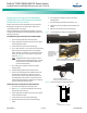
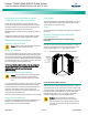
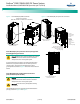
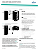
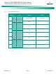
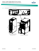
Figure 8. Power Module/Bay IB2 (ACU+ Controller Interface Board) Connections
Power and
Control Section
IB2 (ACU+ Controller
Interface Board) Assembly
(located behing panel)
IB2 I/O Wiring Opening
Rear
Rear door removed in
illustration for clarity only.
Rear
120kW Power Module/Bay
584001200 List 01
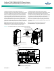
IB2 (ACU+ Controller Interface Board P/N MA4C5U31)
J1
SW1
J11
J12
Relay O
utput
Term. Blocks Digital Input Term.
Blocks
J9 J8 J7 J6 J5 J4 J3
J2
Switch sections must be set to this position
to interface with the ACU+ controller.
Relay
No.
18 7 6 5 4 3 2
18 7 6
5 4 3 2
Input
No
. (
–
)
Input
No. (+)
NO C NC
NO NOC NC
NO C NC
C NC
NO C
NC
NO C NC
NO C NC
NO C NC
5 3 1
46 2
5 3 1
46 2
5 3 1
46 2
5
3
1
46 2
5
3
1
46 2
5 3 1
46 2
5
3
1
4
6 2
8 6
4
2
7 5 3 1
Relay
No.
J3-J9:
Wire Size Capacity: 16-26 AWG (1.5-0.5mm
2
).
Recommended Torque: 2.2 in-lbs (0.25 Nm).