
Installation Manual

NetSure
™
9500 120kW 400V DC Power System
Installation Manual, IM584001200 (Issue AA, April 14, 2014)
Spec. No: 584001200 Code: IM584001200
Model No: 9500 Issue AA, April 14, 2014
[6 of 25]
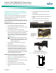
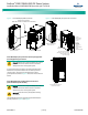
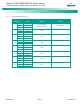
Figure 6. Power Module/Bay DC Load Distribution Connections to
Distribution Panel List 21HA
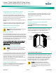
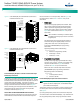
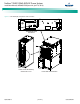
Figure 7. Power Module/Bay DC Load Distribution Connections to
Distribution Panel List 23HA
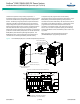
Power Module/Bay IB2 (ACU+ Controller Interface Board P/N
MA4C5U31) Connections
The IB2 (ACU+ Controller Interface Board) provides connection
points for digital inputs and programmable relay outputs. The IB2
interface board is accessed from the rear of the power and control
section of the Power Module/Bay. Loosen the two captive
fasteners and slide the tray the IB2 assembly is mounted to out far
enough to make the electrical connections. Refer to Figure 8.
When connecting input and output wires to the IB2 board, route
the leads through the opening provided in the tray the IB2
assembly is mounted to (see Figure 8).
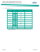
DIGITAL INPUTS AND PROGRAMMABLE RELAY OUTPUTS
Digital input and relay output leads are connected to screw-type
terminal blocks located on the IB2. Recommended torque for
these connections is 2.2 in-lbs (0.25 Nm). Refer to Figure 8 for
terminal locations. Refer to Table 1 and Table 2 for pin-out
information.
•
Digital Inputs
Connect up to eight (8) digital inputs to the IB2. Note
that you must supply both paths for the digital input
(either a positive or negative signal and the opposite
polarity return path). Observe proper polarity. Refer to
Figure 8 for terminal locations and Table 1 for pin-out
information.
Note:
+48V is available on terminal J5-5 and Return (RTN)
is available on terminal J5-6 for customer connection
to digital inputs.
The digital inputs can be programmed to provide an
alarm when the signal is applied (HIGH) or removed
(LOW). Refer to the ACU+ Controller Operation
Instructions (UM1M820NNB-2) for programming
information.
Digital Input Ratings: Refer to the following.
a. Maximum Voltage Rating: 60V DC.
b. Active High: > 19V DC.
c. Active Low: < 1V DC.
• Programmable Relay Outputs
The IB2 provides eight (8) programmable alarm relays
with dry Form-C contacts. Connect up to eight (8) relay
outputs to the IB2. Refer to Figure 8 for terminal
locations and Table 2 for pin-out information.
Refer to the ACU+ Controller Operation Instructions
(UM1M820NNB-2) for programming information.
Relay Ratings: Refer to the following.
a. 1A Steady State @ 30V DC.
b. 3A Peak @ 30V DC.
Power Module/Bay Temperature Probe Connections
Note:
Each temperature probe consists of two pieces that plug
together to make a complete probe. See SAG584001200 for
part numbers and descriptions.
Temperature probes are connected to connectors located on the
rear of the power and control section of the Power Module/Bay.
See Figure 9.
Up to six (6) temperature probes can be connected to the power
and control section of the Power Module/Bay. Any combination of
the six (6) temperature probes can be programmed to monitor
Rear
Positive (+)
Negative (-)
Positive (+)
Bus
Negative (-)
Bus
Recomended Torque:
84 in-lbs (9.5 Nm)
±200V DC
120kW Power Module/Bay
584001200 List 01
Distribution
Panel
Front door removed in
illustration for clarity only.
Customer
Load Connections
to DC Distribution
Circuit Breakers
(M6 studs on
16mm [5/8”] centers)
(left and right sides)
Rear
Negative (-)
Positive (+)
120kW Power Module/Bay
584001200 List 01
Distribution
Panel
Distribution
Panel
Distribution
Panel
Positive (+)
Bus
Negative (-)
Bus
Recomended
Torque:
108 in-lbs (12 Nm)
±200V DC
Front door removed in
illustration for clarity only.
Customer
Load Connection
(M8 studs on
25mm [1”] centers)