
Installation Manual

NetSure
™
9500 120kW 400V DC Power System
Installation Manual, IM584001200 (Issue AA, April 14, 2014)
Spec. No: 584001200 Code: IM584001200
Model No: 9500 Issue AA, April 14, 2014
[5 of 25]
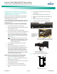
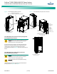
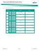
Figure 4. Power Module/Bay HRMG Connection
Power Module/Bay AC Input Power and AC Input Equipment
Grounding/Earthing Connections
Danger! Adhere to the “Important Safety Instructions”
presented at the front of this document. DO NOT
attempt to work on an energized system.
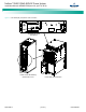
AC input connections are made to AC input terminals located
behind an access panel located on the rear of the power and
control section. Studs are also provided for the AC input
ground/earth lead. Refer to Figure 5 for location and connection
details.
Power Module/Bay DC Load Distribution Connections
(if DC distribution panel installed)
Danger! Adhere to the “Important Safety Instructions”
presented at the front of this document. DO NOT
attempt to work on an energized system.
Warning! Check for correct polarity before making
connections.
Load distribution leads are connected to the load distribution
panel(s) as shown in Figure 6 and Figure 7.
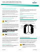
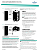
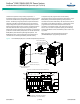
Figure 5. Power Module/Bay AC Input Power Connections
Rear
Rear
Power and Control Section
HRMG Ground Connection
(M
UST BE PROPERLY CONNECTED TO GROUND)
120kW Power Module/Bay
584001200 List 01
AC Input Ground Lead Studs
(M8 studs on 25mm [1”] centers)
(Recommended Torque:
108 in-lbs [12 Nm])
Rear
Rear
AC Input
Leads Opening
for 51mm (2”)
Conduit
AC Input
Terminals
(M8 studs
on 25mm [1”]
centers)
(Recommended
Torque:
108 in-lbs [12 Nm])
Power and
Control Section
L1
L2 L3
AC Input
Nominal 380V/400V/480V AC,
Three-Phase, 50/60 Hz.
Rear
120kW Power Module/Bay
584001200 List 01
Da
ng
e
r
Danger
War
ning