
Installation Manual

NetSure
™
9500 120kW 400V DC Power System
Installation Manual, IM584001200 (Issue AA, April 14, 2014)
Spec. No: 584001200 Code: IM584001200
Model No: 9500 Issue AA, April 14, 2014
[4 of 25]
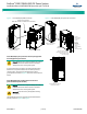
Positioning and Securing the Battery Cabinet
(584001200 List 90, 91, 92, 93) to the Floor
Position and secure the Battery Cabinet to the floor per site
requirements. Refer also to “General Requirements” on page 2.
The Battery Cabinet is furnished with separate installation and
operation instructions. Refer to these instructions
(IM58400120090) to position and secure the Battery Cabinet to
the floor.
A pallet jack or forklift is required to install the Battery Cabinet
(3500 lb capacity; batteries shipped installed in the cabinet).
Making Electrical Connections
Important Safety Instructions
Danger! Adhere to the “Important Safety Instructions”
presented at the front of this document.
Wiring Considerations
All AC input and 400V DC output wiring, branch circuit protection,
and grounding/earthing should follow the current edition of the
American National Standards Institute (ANSI) approved National
Fire Protection Association's (NFPA) National Electrical Code (NEC),
and applicable local codes. For operation in countries where the
NEC is not recognized, follow applicable codes.
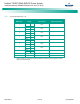
For wire size, branch circuit protection, crimp lug, and general
wiring recommendations; refer to System Application Guide
SAG584001200 and the Battery Cabinet manual
(IM58400120090).
General Grounding/Earthing Guidelines
Danger! Failure to follow proper grounding/earthing
procedures can result in electric shock hazard to
personnel and the risk of fire, should a ground fault
occur.
For grounding/earthing requirements, refer to the current edition
of the American National Standards Institute (ANSI) approved
National Fire Protection Association's (NFPA) National Electrical
Code (NEC), applicable local codes, and your specific site
requirements. For operation in countries where the NEC is not
recognized, follow applicable codes.
Refer also to the grounding/earthing procedures in this document.
Output Ground Configuration
This system is configured for High Resistance Midpoint Ground
(HRMG). Ensure the HRMG lead is properly connected to
ground/earth per the instructions that follow.
Cable Routing
The Power Module/Bay and Distribution Module/Bay are provided
with top plates that have cable routing holes that either accept
conduit fittings or corded connections.
Torque
Torque all connections as specified in the illustrations presented in
this section.
Electrical Connections to Power Module/Bay
(584001200 List 01)
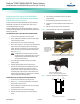
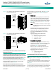
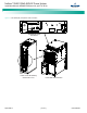
Power Module/Bay Rack Frame Grounding/Earthing
Connection
Refer also to “General Grounding/Earthing Guidelines” on page 4.
Supply a grounding/earthing lead from site ground/earth to the
rack ground bar. Refer to Figure 3 for connection point.
Figure 3. Power Module/Bay Rack Frame Grounding/Earthing
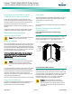
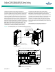
Power Module/Bay HRMG Connection
Refer also to “General Grounding/Earthing Guidelines” on page 4.
A ground lead exits the rear of the power and control section in the
Power Module/Bay. This lead MUST be connected to ground/earth
for proper operation of the HRMG circuit and the ground fault
detection circuit. Refer to Figure 4 for location. THIS LEAD IS
FACTORY CONNECTED TO THE RACK’S GROUND BAR.
Caution! Failure to terminate this conductor to
ground/earth will render the system ground fault
detection circuit and the ±200V DC voltage reference
inoperable. It is essential to properly bond this lead to
ground/earth.
Rear Rear
Ground Bar
(M6 studs on
16mm [5/8”]
centers)
(Recommended
Torque:
84 in-lbs [9.5 Nm])
Ground Bar
(M6 studs on
16mm [5/8”]
centers)
(Recommended
Torque:
84 in-lbs [9.5 Nm])
120kW Power Module/Bay
584001200 List 01
Da
n
ge
r
Caution
D
ang
er