
Installation Manual

NetSure
™
9500 120kW 400V DC Power System
Installation Manual, IM584001200 (Issue AA, April 14, 2014)
Spec. No: 584001200 Code: IM584001200
Model No: 9500 Issue AA, April 14, 2014
[3 of 25]
Positioning and Securing the Power Module/Bay
(584001200 List 01) and Distribution Module/Bay
(584001200 List 07) to the Floor
Position and secure the Power Module/Bay and/or Distribution
Module/Bay to the floor per site requirements. Refer also to
“General Requirements” on page 2.
The Power Module/Bay and Distribution Module/Bay consists of
rack P/N 557861 (standard) or P/N 557858 (Seismic). Refer to the
following procedures.
STANDARD RACK (P/N 557861) INSTALLATION PROCEDURE
1. Use at least two people when moving the rack.
2. Using a pallet jack or forklift, move the rack on its pallet
to the installation location.
3. Cut the shrink wrap and remove all packaging.
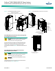
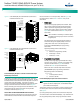
4. Use a 14mm socket or a 14mm wrench to remove the lag
bolts securing each shipping bracket to the shipping
pallet. There are two brackets, one in the front and one
at the rear of the rack. Each bracket is secured by four
bolts (see Figure 1).
Note:
Shipping brackets can also be used as an anchor
bracket once unit is at final resting place. Leave the
shipping brackets attached if they will be used to
secure the rack to the floor.
5. Use a pallet jack or forklift to raise the rack off the
shipping pallet.
6. Slide the shipping pallet out from under the rack.
7. The rack may be positioned for installation either with
the pallet jack or forklift or by rolling the rack on its
casters. If the casters are to be used to move the rack,
the leveling feet must be raised. Position the rack and
either lower the leveling feet or bolt the rack to the floor
with the shipping/anchoring brackets.
SEISMIC RACK (P/N 557858) INSTALLATION PROCEDURE
1. Use at least two people when moving the rack.
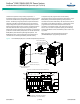
2. Refer to Figure 2 and prepare the floor for the anchors
being used to secure the rack.
3. Using a pallet jack or forklift, move the rack on its pallet
to the installation location.
4. Cut the shrink wrap and remove all packaging.
5. Remove the bolts securing the rack to the shipping
pallet.
6. Use a pallet jack or forklift to raise the rack off the
shipping pallet.
7. Slide the shipping pallet out from under the rack.
8. Position the rack for installation with the pallet jack or
forklift.
9. Bolt the rack to the floor per site requirements.
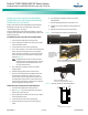
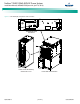
Figure 1. Removing Rack P/N 557861 from Shipping Pallet
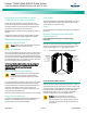
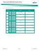
Figure 2. Rack P/N 557858 Floor Hole Drilling Pattern
Rack will rest on casters wh
en
re
moving the shipping/bolt-down bracket.
Shippi
ng/
Anch
or
Br
ac
ke
t
Remove lag bo
lts
from
brackets on front and rear of
the
rack to free the shipping bracket
from
the p
allet.
Leave brackets
bolted to the rack
if they will be use
d
to secure
the rack
to the
floor.
Notes:
1. Dimensions are in mm (inches).
Bottom View
441
(17.37)
84
(3.314)
84
(3.314)
898
(35.37)