
Application Guide


Table Of Contents
- Section 5877 (Issue AQ) CH01.pdf
- CHAPTER 1 SYSTEM OVERVIEW
- Table of Contents
- Preface
- System Description
- System Overview Illustrations
- Power/Distribution Bay
- Power Only Bay
- Distribution Only Bay
- Detail A - Distribution Bus Monitoring Circuit Card
- Detail B - System Monitoring and Control Section
- Detail C - Monitoring and Control Section (Distribution Only Bays)
- Detail D - Front Door (Primary Power/Distribution and Power Only Bays) MCA Control Panel and Display
- Detail E - MCA Circuit Card (Primary Power/Distribution and Power Only Bays) and Router Circuit Card (Secondary Power/Distribution and Power Only Bays and Distribution Only Bays)
- Detail F
- Details G - MCA I/O Circuit Cards
- Detail H - LMS I/O Circuit Cards
- Detail I1 - LMS 4 Input Analog Circuit Card (P/N 506336)
- Detail I2 - LMS 8 Input Analog Circuit Card (P/N 514528)
- Detail I3 - LMS 8 Input Temperature Circuit Card (P/N 506333)
- Detail I4 - LMS 4 Input Binary Circuit Card (P/N 506332)
- Detail I5 - LMS 8 Input Binary Circuit Card (P/N 506334)
- Detail I6 - LMS 4 Output Relay Circuit Card (P/N 506335)
- Detail I7 - LMS 12 Input Analog Circuit Card (P/N 520838)
- Detail J - Rectifier
- CHAPTER 1 SYSTEM OVERVIEW
- Section 5877 (Issue AQ) CH02.pdf
- Section 5877 (Issue AQ) CH03.pdf
- CHAPTER 3 SYSTEM OPERATING PROCEDURES
- Table of Contents
- LMS Operating Procedures
- LMS Local Port
- Local Controls and Indicators
- Location and Identification
- LMS Main/Expansion CPU Circuit Card (if furnished) Controls and Indicators
- Bay LED Indicator
- Distribution Bus LED Indicator
- MCA Component LED Indicator
- Bay Monitoring and Control Section Indicators
- MCA Controls and Indicators
- MCA Display
- Surge Suppression Alarms (available only if a Surge Suppression Option is furnished)
- Rectifier Controls and Indicators
- External Alarms
- Starting and Stopping System Operation
- Restarting Procedures when Rectifier is Automatically or Manually Inhibited, Shut Down, or Locked Out
- Output Voltage Mode of Operation Selection
- Setting MCA Audible Alarm Cutoff Reset Time Period
- Setting Rectifier Sequencing Delay Time Period
- Setting MCA Custom Text Messages (Names)
- Mapping LMS LED Channels to the MCA Display and MCA Customer Alarm Relays
- Using the Alarm Relay Test Feature
- MCA “Power Share” Feature
- MCA “ALTERNATE CURRENT LIMIT” FEATURE
- CHAPTER 3 SYSTEM OPERATING PROCEDURES
- Section 5877 (Issue AQ) CH04.pdf
- CHAPTER 4 MCA SYSTEM ADJUSTMENTS
- Table of Contents
- Adjustment Location and Identification
- Adjusting Float Output Voltage
- Adjusting Test/Equalize Output Voltage
- Adjusting High Voltage Shutdown
- Adjusting Rectifier Current Limit
- Adjusting System High Voltage Alarm 1
- Adjusting System High Voltage Alarm 2
- Adjusting System Battery On Discharge Alarm
- Adjusting System Very Low Voltage Alarm
- Adjusting Total Distribution Load Alarm
- Adjusting Distribution Group A Load Alarm
- Adjusting Distribution Group B Load Alarm
- Adjusting Battery Ambient High Temperature #1 Alarm (if Battery Charge Digital Temperature Compensation Probe is installed)
- Adjusting Battery Ambient High Temperature #2 Alarm (if Battery Charge Digital Temperature Compensation Probe is installed)
- Adjusting Battery Ambient Low Temperature #1 Alarm (if Battery Charge Digital Temperature Compensation Probe is installed)
- Adjusting Battery Ambient Low Temperature #2 Alarm (if Battery Charge Digital Temperature Compensation Probe is installed)
- Configuring Battery Charge Digital Temperature Compensation Slope
- Configuring Battery Charge Digital Temperature Compensation Maximum Voltage
- Configuring Battery Charge Digital Temperature Compensation Minimum Voltage
- Configuring Degree Units Displayed ((F or (C)
- Configuring the System Date and Time
- Configuring MCA I/O Circuit Card Analog Input(s)
- Configuring MCA I/O Circuit Card Analog Output(s)
- Configuring MCA I/O Circuit Card Binary Input(s)
- MCA Audible Alarm Cutoff Reset Time Period
- MCA Rectifier Sequencing Feature
- Manually Initiated Timed Test/Equalize Feature
- Automatic Test/Equalize Feature
- MCA Power Share Feature
- Alarm Relay Test Feature
- MCA “Alternate Current Limit” Feature
- CHAPTER 4 MCA SYSTEM ADJUSTMENTS
- Section 5877 (Issue AQ) CH05.pdf
- Section 5877 (Issue AQ) CH06.pdf
- CHAPTER 6 SYSTEM TROUBLESHOOTING AND REPAIR
- Contact Information
- Table of Contents
- Admonishments
- LMS Troubleshooting Procedures
- Troubleshooting Information
- Replacement Information
- Replacement Procedures
- Adding a Battery Charge Digital Temperature Compensation Probe to a Previously Operated System
- Removing a Battery Charge Digital Temperature Compensation Probe from a Previously Operated System
- CHAPTER 6 SYSTEM TROUBLESHOOTING AND REPAIR
User Instructions Section 5877
Spec. No. 582140000 (Models 802NLDB, 802NLEB and 802NL-B) Issue AQ, January 15, 2013
Chapter 2. Navigating the MCA Page 2-1
This document is property of Emerson Network Power, Energy Systems, North America, Inc. and contains confidential and proprietary information owned by Emerson Network Power, Energy
Systems, North America, Inc. Any copying, use, or disclosure of it without the written permission of Emerson Network Power, Energy Systems, North America, Inc. is strictly prohibited.
CHAPTER 2
0BNAVIGATING THE MCA
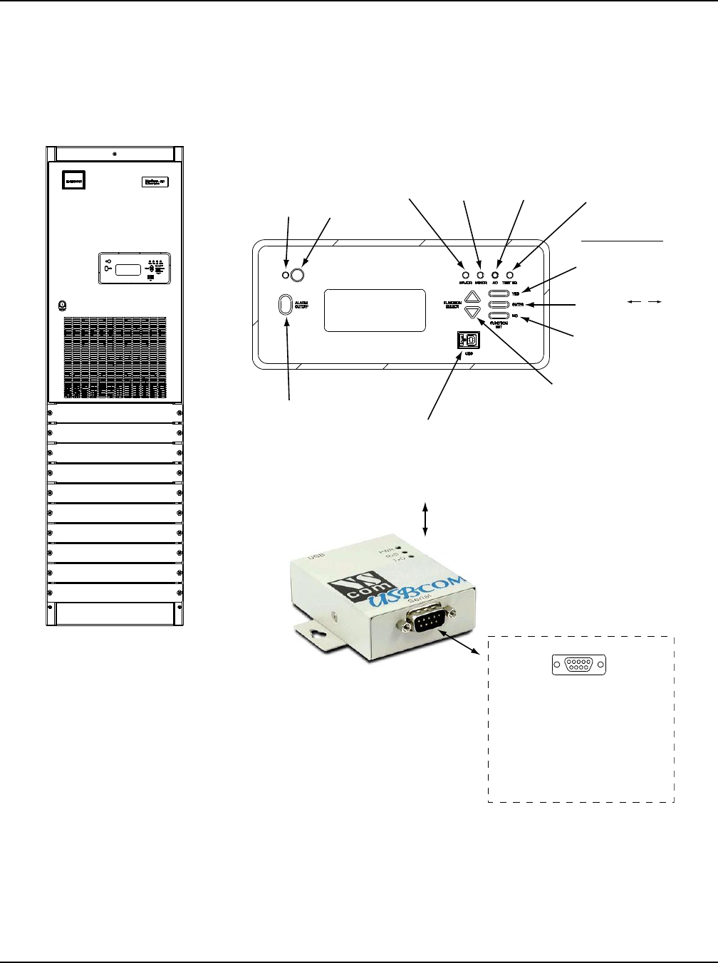
1BMCA LOCAL CONTROL PANEL AND DISPLAY
Located on the Primary Power/Distribution and Power Only Bays’ front door.
Navigating the MCA is an easy process. You just have to remember a few key
combinations (as shown in the following chart). The symbols that appear at the end of
the fourth line of the display indicate which keypad buttons can be pressed at any given
time.
Alarm
Cutoff
Indicator
(Yellow)
FUNCTION SET
YES / + / i
Pushbutton Switch
ENTER / /
Pushbutton Switch
NO / -
Pushbutton Switch
ALARM
CUTOFF
Pushbutton
Switch
FUNCTION
SELECT
Up / Down
Pushbutton
Switches
TESTEQ
Indicator
(Yellow)
AC
Indicator
(Green - OK
Red - Fail)
MINOR
Indicator
(Red)
MAJOR
Indicator
(Flashes
Red)
Audible
Alarm
FRONT DOOR
(PRIMARY POWER/DISTRIBUTION AND POWER ONLY BAYS)
MCA CONTROL PANEL AND DISPLAY
LMS LOCAL PORT
(USB)
(active only if
optional LMS installed)
(Provided via a USB Type B to RS-232 Port Adapter Unit)
15
9 6
Mating Connector
in Power System Wire Harness
(9-Pin Female D-Type Jack)
If required to connect to a serial
port, disconnect the factory plug to
the “USB to RS-232 Port Adapter
Unit” and connect to this plug.