
Application Guide
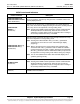


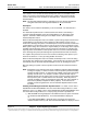
Table Of Contents
- Section 5877 (Issue AQ) CH01.pdf
- CHAPTER 1 SYSTEM OVERVIEW
- Table of Contents
- Preface
- System Description
- System Overview Illustrations
- Power/Distribution Bay
- Power Only Bay
- Distribution Only Bay
- Detail A - Distribution Bus Monitoring Circuit Card
- Detail B - System Monitoring and Control Section
- Detail C - Monitoring and Control Section (Distribution Only Bays)
- Detail D - Front Door (Primary Power/Distribution and Power Only Bays) MCA Control Panel and Display
- Detail E - MCA Circuit Card (Primary Power/Distribution and Power Only Bays) and Router Circuit Card (Secondary Power/Distribution and Power Only Bays and Distribution Only Bays)
- Detail F
- Details G - MCA I/O Circuit Cards
- Detail H - LMS I/O Circuit Cards
- Detail I1 - LMS 4 Input Analog Circuit Card (P/N 506336)
- Detail I2 - LMS 8 Input Analog Circuit Card (P/N 514528)
- Detail I3 - LMS 8 Input Temperature Circuit Card (P/N 506333)
- Detail I4 - LMS 4 Input Binary Circuit Card (P/N 506332)
- Detail I5 - LMS 8 Input Binary Circuit Card (P/N 506334)
- Detail I6 - LMS 4 Output Relay Circuit Card (P/N 506335)
- Detail I7 - LMS 12 Input Analog Circuit Card (P/N 520838)
- Detail J - Rectifier
- CHAPTER 1 SYSTEM OVERVIEW
- Section 5877 (Issue AQ) CH02.pdf
- Section 5877 (Issue AQ) CH03.pdf
- CHAPTER 3 SYSTEM OPERATING PROCEDURES
- Table of Contents
- LMS Operating Procedures
- LMS Local Port
- Local Controls and Indicators
- Location and Identification
- LMS Main/Expansion CPU Circuit Card (if furnished) Controls and Indicators
- Bay LED Indicator
- Distribution Bus LED Indicator
- MCA Component LED Indicator
- Bay Monitoring and Control Section Indicators
- MCA Controls and Indicators
- MCA Display
- Surge Suppression Alarms (available only if a Surge Suppression Option is furnished)
- Rectifier Controls and Indicators
- External Alarms
- Starting and Stopping System Operation
- Restarting Procedures when Rectifier is Automatically or Manually Inhibited, Shut Down, or Locked Out
- Output Voltage Mode of Operation Selection
- Setting MCA Audible Alarm Cutoff Reset Time Period
- Setting Rectifier Sequencing Delay Time Period
- Setting MCA Custom Text Messages (Names)
- Mapping LMS LED Channels to the MCA Display and MCA Customer Alarm Relays
- Using the Alarm Relay Test Feature
- MCA “Power Share” Feature
- MCA “ALTERNATE CURRENT LIMIT” FEATURE
- CHAPTER 3 SYSTEM OPERATING PROCEDURES
- Section 5877 (Issue AQ) CH04.pdf
- CHAPTER 4 MCA SYSTEM ADJUSTMENTS
- Table of Contents
- Adjustment Location and Identification
- Adjusting Float Output Voltage
- Adjusting Test/Equalize Output Voltage
- Adjusting High Voltage Shutdown
- Adjusting Rectifier Current Limit
- Adjusting System High Voltage Alarm 1
- Adjusting System High Voltage Alarm 2
- Adjusting System Battery On Discharge Alarm
- Adjusting System Very Low Voltage Alarm
- Adjusting Total Distribution Load Alarm
- Adjusting Distribution Group A Load Alarm
- Adjusting Distribution Group B Load Alarm
- Adjusting Battery Ambient High Temperature #1 Alarm (if Battery Charge Digital Temperature Compensation Probe is installed)
- Adjusting Battery Ambient High Temperature #2 Alarm (if Battery Charge Digital Temperature Compensation Probe is installed)
- Adjusting Battery Ambient Low Temperature #1 Alarm (if Battery Charge Digital Temperature Compensation Probe is installed)
- Adjusting Battery Ambient Low Temperature #2 Alarm (if Battery Charge Digital Temperature Compensation Probe is installed)
- Configuring Battery Charge Digital Temperature Compensation Slope
- Configuring Battery Charge Digital Temperature Compensation Maximum Voltage
- Configuring Battery Charge Digital Temperature Compensation Minimum Voltage
- Configuring Degree Units Displayed ((F or (C)
- Configuring the System Date and Time
- Configuring MCA I/O Circuit Card Analog Input(s)
- Configuring MCA I/O Circuit Card Analog Output(s)
- Configuring MCA I/O Circuit Card Binary Input(s)
- MCA Audible Alarm Cutoff Reset Time Period
- MCA Rectifier Sequencing Feature
- Manually Initiated Timed Test/Equalize Feature
- Automatic Test/Equalize Feature
- MCA Power Share Feature
- Alarm Relay Test Feature
- MCA “Alternate Current Limit” Feature
- CHAPTER 4 MCA SYSTEM ADJUSTMENTS
- Section 5877 (Issue AQ) CH05.pdf
- Section 5877 (Issue AQ) CH06.pdf
- CHAPTER 6 SYSTEM TROUBLESHOOTING AND REPAIR
- Contact Information
- Table of Contents
- Admonishments
- LMS Troubleshooting Procedures
- Troubleshooting Information
- Replacement Information
- Replacement Procedures
- Adding a Battery Charge Digital Temperature Compensation Probe to a Previously Operated System
- Removing a Battery Charge Digital Temperature Compensation Probe from a Previously Operated System
- CHAPTER 6 SYSTEM TROUBLESHOOTING AND REPAIR

Section 5877 User Instructions
Issue AQ, January 15, 2013 Spec. No. 582140000 (Models 802NLDB, 802NLEB and 802NL-B)
Page 3-6 Chapter 3. System Operating Procedures
This document is property of Emerson Network Power, Energy Systems, North America, Inc. and contains confidential and proprietary information owned by Emerson Network Power, Energy
Systems, North America, Inc. Any copying, use, or disclosure of it without the written permission of Emerson Network Power, Energy Systems, North America, Inc. is strictly prohibited.
MAJOR
(Indicator)
Flashes red if any condition listed below occurs.
AC fail on two or more Rectifiers.
Rectifier fail alarm activates on two or more Rectifiers.
Battery On Discharge alarm activates.
Very Low Voltage alarm activates.
High Voltage Alarm 1 activates.
High Voltage Alarm 2 activates.
Emergency Stop or Remote HVS activated.
If any system distribution fuse or circuit breaker opens.
Any High or Low Temperature Alarm activates.
Any Router, Distribution, MCA Relay, or MCA I/O circuit card alarm
activates.
Duplicate Rectifier, Router, Distribution, MCA Relay, or MCA I/O circuit
card reference designation.
System component cannot be identified.
MCA Hardware/Software failure.
MCA Initializing.
MINOR
(Indicator)
Illuminates red if any condition listed below occurs.
Rectifier fail alarm activates on any single Rectifier.
If the over-current alarm activates.
Loss of communication to the display or LMS.
AC
(Indicator)
Illuminates green if AC input voltage to all Rectifiers is greater than the preset
non-adjustable low AC input voltage inhibit, less than the preset non-
adjustable high AC input voltage inhibit, and the Standby/Operate switch on
each Rectifier is in the I "operate" position. Illuminates red if AC input voltage
to any Rectifier decreases below or increases above the respective inhibit
value.
Danger: In standby mode, AC input power IS connected to the Rectifier.
TEST/EQ
(Indicator)
Illuminates yellow when the system is placed in the test/equalize mode, locally
or remotely.
MCA Display
Refer to Chapter 2. Navigating the MCA for MCA Display descriptions.
Surge Suppression Alarms
(available only if a Surge Suppression Option is furnished)
If a surge suppression assembly operates, the MCA displays a "Binary Input Customer
Text Message" in the I/O Board Alarm Detail Message. If you wish to change the default
message, refer to the " SETTING MCA CUSTOM TEXT MESSAGES " in this chapter.
"MCA Customer Alarm Relays" may also be programmed to provide an external alarm.
Note that a Surge Suppression Alarm is active when there is NO AC power, and
resets when AC power is supplied.