
Application Guide


Section 5876 Installation Instructions
Issue AT, April 26, 2013 Spec. No. 582140000 (Models 802
NLDB, 802NLEB and 802NL-B)
Page 4-32 Chapter 4. Making Electrical Connections
This document is property of Emerson Network Power, Energy Systems, North America, Inc. and contains confidential and proprietary information owned by Emerson Network Power, Energy
Systems, North America, Inc. Any copying, use, or disclosure of it without the written permission of Emerson Network Power, Energy Systems, North America, Inc. is strictly prohibited.
BAY FRAME GROUNDING CONNECTIONS
Note: Refer to System Application Guide SAG582140000 for recommended wire size
and crimp lug. Refer to drawing 031110100 for lug crimping information. Refer to
drawings 031110200 and 031110300 for additional lug information. The SAG and
Engineering Drawings can be accessed via the CD (Electronic Documentation
Package) furnished with your system. A copy of drawing 031110100 is also
located at the end of this manual for your convenience.
For bay grounding requirements; refer to the National Electrical Code, applicable
local codes, and your specific site requirements.
Procedure
Located on the top of each bay are two to four sets of captive nuts (1/4-20 on 5/8"
centers) or holes. Attach customer grounding network leads to these using customer
supplied two-hole lugs, mounting bolts, and hardware. Recommended torque is 60 in-lbs
when using 1/4-inch hardware and a Belleville lock washer.
Refer to Figure 4-8 and Figure 4-9 for location.
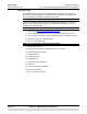
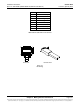
Figure 4-8
Power/Distribution and Power Only Bay Frame Grounding Connection Locations
Two holes with 1/4-20 ca
ptive
nuts provided for installation of
customer provided two-hole lug
with 1/4" bolt clearance holes
on 5/8" centers
Two holes with 1/4-20 captive
nuts provided for installation of
customer provided two-hole lug
with 1/4" bolt clearance holes
on 5/8" centers
Top View
Recm. Torque
1/4" Hardware
using Belleville
Lock Washer
60 in-lbs.
Power/Distribution Bay Shown,
Power Only Bay Similar