
Application Guide


Installation Instructions Section 5876
Spec. No. 582140000 (Models 802
NLDB, 802NLEB and 802NL-B) Issue AT, April 26, 2013
Chapter 4. Making Electrical Connections Page 4-29
This document is property of Emerson Network Power, Energy Systems, North America, Inc. and contains confidential and proprietary information owned by Emerson Network Power, Energy
Systems, North America, Inc. Any copying, use, or disclosure of it without the written permission of Emerson Network Power, Energy Systems, North America, Inc. is strictly prohibited.
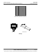
LMS Network Interconnections Between Bays
and Optional LMS Expansion Assembly(s)
Between Bays
An LMS Network cable must be installed between all bays with LMS CPU circuit cards
installed, as detailed in the following procedure. Pre-assembled cables are available.
Refer to System Application Guide SAG582140000 for P/N's. The SAG can be accessed
via the CD (Electronic Documentation Package) furnished with your system. Refer to
"LMS Network Cable Assembly Instructions" in this section to assemble your own cable.
Note: Refer to
Procedure
Figure 4-6 as this procedure is performed.
1) Open all bays' front doors containing LMS CPU circuit cards.
2) Connect a furnished LMS Network cable (this is a blue cable) between bays
containing LMS CPU circuit cards. There a three (3) LMS Network ports located
in each bay. Any of these ports can be used in multitude of configurations to
interconnect the bays. Refer to Figure 4-6 for typical interconnections. Refer to
System Application Guide SAG586505000 for maximum combined cable length
restrictions. The SAG can be accessed via the CD (Electronic Documentation
Package) furnished with your system.
a) Connect one end of the cable to an LMS Network Port in the first bay. Note
that there are three connectors, use any open connector.
b) Route the cable through the opening provided in the side of the bay into the
next bay. If PDSCs (AC Input 'Power Distribution Service Cabinets') are
provided, route the cable through the metal channel provided in the PDSC
and into the next bay.
c) Connect the other end of the cable to an LMS Network Port in the second
bay. Note that there are three connectors, use any open connector.
3) Connect all bays containing LMS CPU circuit cards together in this fashion.
4) If no other connections are required within the bays, close all bays' front doors.
To Optional LMS Expansion Assembly(s)
Any optional LMS Expansion Assembly(s) must be interconnected into the LMS Network,
as detailed in the following procedure. Pre-assembled cables are available. Refer to
System Application Guide SAG582140000 for P/N's. The SAG can be accessed via the
CD (Electronic Documentation Package) furnished with your system. Refer to "LMS
Network Cable Assembly Instructions" in this section to assemble your own cable.
Note: Refer to
Procedure
Figure 4-6 as this procedure is performed.
1) Connect a furnished LMS Network cable (this is a blue cable) between a bay
containing an LMS CPU circuit card and the optional LMS Expansion Assembly.
There a three (3) LMS Network ports located in each bay. Any of these ports can
be used in multitude of configurations to interconnect the optional LMS
Expansion Assembly. Refer to Figure 4-6 for typical interconnections. Refer to
System Application Guide SAG586505000 for maximum combined cable length
restrictions. The SAG can be accessed via the CD (Electronic Documentation
Package) furnished with your system.