
Application Guide


Section 5876 Installation Instructions
Issue AT, April 26, 2013 Spec. No. 582140000 (Models 802
NLDB, 802NLEB and 802NL-B)
Page 4-26 Chapter 4. Making Electrical Connections
This document is property of Emerson Network Power, Energy Systems, North America, Inc. and contains confidential and proprietary information owned by Emerson Network Power, Energy
Systems, North America, Inc. Any copying, use, or disclosure of it without the written permission of Emerson Network Power, Energy Systems, North America, Inc. is strictly prohibited.
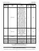
Figure 4-6 (cont'd from previous page, cont'd on next page)
LMS Connection Points
Detail C
LMS Monitoring System
Main CPU Circuit Card
(P/N 545558)
(Primary Bay Only)
LMS Modem
Port (RJ-11)
(Phone Line)
Piggy-Back Modem
Circuit Card
(P/N 508951)
5 1
9 6
9-Pin Female D-Type Jack
RS-232
J4
(located
behind
bracket)
NO C NC
J4
External
CPU/Harware Fail Alarm
1 2 3 4 5 6
Relay contacts are shown
with the realy de-energized.
Relay contacts are energized
during normal operation and
de-energized during an alarm
condition.
NC = Normally Closed
C = Common
NO = Normally
Open
Notes