
Application Guide


SAG582140000 System Application Guide
Issue AW, June 3, 2014 Spec. No. 582140000 (Models 802
NLDB, 802NLEB and 802NL-B)
Page 112 of 134
This document is property of Emerson Network Power, Energy Systems, North America, Inc. and contains confidential and proprietary information owned by Emerson Network Power, Energy
Systems, North America, Inc. Any copying, use, or disclosure of it without the written permission of Emerson Network Power, Energy Systems, North America, Inc. is strictly prohibited.
4. MCA
4.1 Standard Features
4.1.1 MCA Interface: You interface with the MCA locally via the MCA Control Panel located on the
outside of the primary Power/Distribution Bay's front door.
You can also interface with the MCA via the LMS, if furnished.
Note: Option switches are provided to lockout changing adjustment/configuration/calibration
settings via the MCA control panel and/or via the LMS.
4.1.2 MCA Local Display: Provides digital metering of system load voltage and current, individual
Rectifier output, and individual load shunts. Also displays system alarm messages and
adjustment information, as detailed in Paragraph 4.1.12 (MCA Display).
4.1.3 MCA Meter Accuracy: ±0.01 V, ±0.005% / °C
4.1.4 MCA Remote Sense Maximum Voltage Drop Compensation: The maximum voltage drop
that the Remote Sense can compensate is 400mV for 48V systems and 200mV for 24V
systems.
4.1.5 MCA Universal Adjustment Circuit: Provides single point control of float output voltage,
test/equalize output voltage, high voltage shutdown, and current limit adjustments.
Note: If the MCA should fail, the Rectifiers remember the float and high voltage shutdown
settings last delivered by the MCA. The current limit setting of each Rectifier goes to
100% of rated full load.
Provides adjustments for all MCA alarm and control circuits. Adjustment ranges and factory
settings as follows.
All adjustments can be performed locally via the MCA Control Panel, and most can be
performed remotely via the LMS (if furnished).
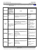
(A) System High Voltage #1 Alarm: Adjustable from 48.00 to 59.00 volts DC. Factory set at
55.5 volts, unless otherwise specified.
(B) System High Voltage #2 Alarm: Adjustable from 48.00 to 59.00 volts DC. Factory set at
56.5 volts, unless otherwise specified.
(C) Battery On Discharge Alarm: Adjustable from 40.00 to 56.00 volts DC. Factory set at
51.0 volts, unless otherwise specified.
(D) Very Low Voltage Alarm: Adjustable from 40.00 to 56.00 volts DC. Factory set at 47.0
volts, unless otherwise specified.
(E) Total Distribution Load Alarm: Adjustable from 0 to 60000 amperes. Factory set at
2000 amperes, unless otherwise specified.
(F) Distribution Group A Load Alarm: Adjustable from 0 to 60000 amperes. Factory set at
2000 amperes, unless otherwise specified.
(G) Distribution Group B Load Alarm: Adjustable from 0 to 60000 amperes. Factory set at
2000 amperes, unless otherwise specified.
(H) High Battery Ambient Temperature #1 Alarm (if battery charge digital temperature
compensation probe installed): Adjustable from -50°C to +99°C. You disable the
feature by selecting the setting above +99°C. Factory set to off, unless otherwise
specified.
(I) High Battery Ambient Temperature #2 Alarm (if battery charge digital temperature
compensation probe installed): Adjustable from -50°C to +99°C. You disable the
feature by selecting the setting above +99°C. Factory set to off, unless otherwise
specified.
(J) Low Battery Ambient Temperature #1 Alarm (if battery charge digital temperature
compensation probe installed): Adjustable from -49°C to +100°C. You disable the
feature by selecting the setting below -49°C. Factory set to off, unless otherwise specified.
Home