
Application Guide


System Application Guide SAG582140000
Spec. No. 582140000 (Models 802
NLDB, 802NLEB and 802NL-B) Issue AW, June 3, 2014
Page 109 of 134
This document is property of Emerson Network Power, Energy Systems, North America, Inc. and contains confidential and proprietary information owned by Emerson Network Power, Energy
Systems, North America, Inc. Any copying, use, or disclosure of it without the written permission of Emerson Network Power, Energy Systems, North America, Inc. is strictly prohibited.
3.5.5 Input Protection: Lists 1 and 11 provide connections for up to ten AC input branch
circuits, one per Rectifier mounting position. Customer to provide AC input branch
circuit protection.
Lists 2 and 12 must be used with a PDSC (AC Input 'Power Distribution Service Cabinet').
This cabinet provides connections for one or two AC input branch circuits. A 30 ampere AC
input circuit breaker with an interrupting capacity of 22kA (List 30) or 65kA (List 31) amperes at
480 volts AC is provided for each Rectifier mounting position.
(A) Low AC Input Voltage Inhibit: If AC input voltage decreases to a preset non-adjustable
value, the Rectifier's power conversion circuitry inhibits, disabling system output. When AC
input voltage increases to another preset non-adjustable value, the system automatically
restarts.
(1) 480VAC Input (R48-11600): Designed to inhibit at approximately 385 volts AC, and to
restart at approximately 400 volts AC.
(2) 480VAC Input (R48-12000e): Designed to inhibit at approximately 255 volts AC, and
to restart at approximately 260 volts AC.
(3) 208VAC Input (R48-12000Le): Designed to inhibit at approximately 138 volts AC, and
to restart at approximately 157 volts AC. (Note: In the range of 140 to 180V, the output
is de-rated to 50%.)
(B) High AC Input Voltage Inhibit: If AC input voltage increases to a preset non-adjustable
value, the Rectifier's power conversion circuitry inhibits, disabling system output. When AC
input voltage decreases to another preset non-adjustable value, the system automatically
restarts.
(1) 480VAC Input: Designed to inhibit at approximately 550 volts AC, and to restart at
approximately 535 volts AC.
(2) 208VAC Input: Designed to inhibit at approximately 264 volts AC, and to restart at
approximately 250 volts AC.
(C) Phase Loss: If any of the three phases of the AC input voltage decreases below the lower
limit or increases above the upper limit in Paragraph 3.2.1, the Rectifier's power conversion
circuitry inhibits, disabling system output. When the phase is restored, the system
automatically restarts.
3.5.6 Output Protection
(A) Current Limiting: The maximum current delivered by the system can be programmed
from 10% to 110% of total system capacity. The MCA automatically adjusts the current
limit circuit on each Rectifier so that this value is not exceeded. If a Rectifier fails, the MCA
automatically resets each remaining Rectifier's current limit point to maintain this value.
The MCA also insures that the current limit circuit on any Rectifier is not set above 110% of
its capacity. The default current limit setting is the sum of each installed Rectifier's output
rating. If an additional Rectifier is added to the system, the system current limit is
automatically increased by the rating of the new Rectifier and the new current limit value is
displayed.
The current limiting point can be adjusted without removing a Rectifier. One adjustment
changes the setting of all Rectifiers.
The current limit is factory set at 100% of rated full load, unless otherwise specified.
(B) Output Fusing: Output fusing is provided in each Rectifier. If a fuse opens, local and
remote Rectifier Fail Alarms activate. This fusing is not customer replaceable.
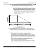
(C) Thermal Current Limiting: Each Rectifier continuously monitors the ambient temperature
surrounding the power conversion unit circuit. If this temperature for any reason (such as a
high ambient office temperature) increases above approximately +40°C (+104°F), the
Rectifier will not shut down. Rather, the Rectifier will limit its maximum output current to
maintain the temperature of the power conversion circuit within design parameters. Full
current capability is restored when the temperature decreases to below approximately
+40°C (+104°F). The following figure illustrates typical operating parameters.
Home
Home