
Brochures and Data Sheets


NetSure
™
ACU+ Controller (Advanced Control Unit Plus)
User Instructions, UM1M820BNA (Issue AK, March 3, 2014)
Spec. No: 1M820BNA, 1M820DNA Code: UM1M820BNA
Model No: M820B, M820D Issue AK, March 3, 2014
88
•
Rect Expansion
•
Inactive:
Select this option if this is the only ACU+
Controller in the power system.
•
Primary:
Select this option if the power system
consists of multiple bays with multiple ACU+
Controllers, and this ACU+ Controller is to be the
Primary Controller. Note that only one (1) ACU+
Controller can be set as the Primary Controller.
•
Secondary:
Select this option if the power system
consists of multiple bays with multiple ACU+
Controllers, and this ACU+ Controller is to be a
Secondary Controller.
_____________________
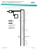
Up to four (4) ACU+ Controllers can be connected
together when a power system requires a greater
number of rectifiers than can be controlled by a single
ACU+ Controller. One (1) Controller is designated as the
primary Controller, the others as secondary Controllers.
The rectifiers controlled by the secondary Controllers are
designated as RectifierGroup 2 through 4 in the menus.
Primary/Secondary Procedure:
Note:
Changing the Rectifier Expansion setting may take
more than 3 minutes for the ACU+ to configure the
feature.
1. Connect the ACU+ Controllers in the multiple bays
via the RS485 interface.
2. Set one of the ACU+ Controllers as the Primary
Controller via the
Rect Expansion
menu item in the
Power System "General" Parameters
menu.
3. Set all other ACU+ Controllers as Secondary
Controllers via the
Rect Expansion
menu item in the
Power System "General" Parameters
menu.
4. Set the Address of the ACU+ Controllers set as
Secondary Controllers to 201, 202, or 203 via the
Address (Slave)
menu item in the
Power System
"General" Parameters
menu. Note that each
Secondary Controller must be set to a different
address.
_____________________
•
Address (Slave):
Sets the address of an ACU+ Controller
set as a Secondary Controller.
•
Over Voltage 1:
Sets the Over Voltage 1 alarm point.
•
Over Voltage 2:
Sets the Over Voltage 2 alarm point.
•
Under Voltage 1:
Sets the Under Voltage 1 alarm point.
•
Under Voltage 2:
Sets the Under Voltage 2 alarm point.
•
Fail Safe:
When enabled, sets the relay designated as the
"critical summary" alarm relay to operate in the "fail safe"
mode. In this mode, the relay is energized during normal
operation and de-energized for an alarm condition.
•
Hybrid Mode:
Refer to “Hybrid Control Function” on page
6 for more information on the Hybrid Mode.
•
Disable / Fixed Daily / Capacity:
Sets the Hybrid
Mode or disables the function.
•
DG Run Overtemp:
Enables or disables diesel
generator operation in an over temperature
condition.
•
DG Run Time:
Sets the diesel generator run time.
•
DG Used:
Sets the diesel generator(s) to be utilized.
•
DI for Grid:
Sets the digital input monitoring the
grid.
•
DOD:
Sets the Depth of Discharge.
•
Dsch Duration:
Sets the discharge duration.
•
Start Dsch Time:
Sets the start time for discharge.
•
High Load Set:
Sets the high load point.
•
Equal StartTime:
Sets the start time for equalizing.
•
DG Alarm Delay:
Sets the diesel generator alarm
delay.
•
Fail Safe:
Tells the Controller the fail safe mode of
the relay contacts connected to start the
generator(s) (either normally open or normally
close).
•
Contactor Mode:
Enables or disables the Power Split
feature (“master control” indicates the ACU+ system
operates normally and “slave control” indicates the ACU+
system is a slave system of the existing legacy system).
See also “Power Split Feature” on page 6.
•
Relay Test:
Sets the Relay Test feature to Automatic,
Individual, or disables the feature.
•
Relay Test Time:
Sets the Relay Test Time for the
Automatic Relay Test feature.
•
HighLoadLevel1:
Sets the High Load Level 1 alarm.
•
HighLoadLevel2:
Sets the High Load Level 2 alarm.
•
DI1 through D18 Alarm State:
Sets the alarm state for the
digital input (high or low).
•
Amb Temp Sensor:
Sets the temperature sensor which
displays the ambient temperature on the Web Interface’s
Homepage. Note that this temperature sensor MUST be
set as an ambient temperature sensor. Select "None", or
the temperature probe (SMTemp8 T8 / ... / SMTemp8 T1
/ ... / SMTemp1 T8 / ... / SMTemp1 T1 / EIB T2 / EIB T1 /
IB2 T2 / IB2 T1). You can also select Maximum or Average