
Brochures and Data Sheets


NetSure
™
ACU+ Controller (Advanced Control Unit Plus)
User Instructions, UM1M820BNA (Issue AK, March 3, 2014)
Spec. No: 1M820BNA, 1M820DNA Code: UM1M820BNA
Model No: M820B, M820D Issue AK, March 3, 2014
81
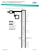
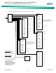
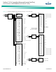
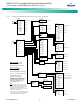
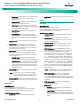
Figure 9. Local Menu Flow Diagrams (cont’d from previous page, cont’d on next page)
Alarm Setting
Alm Severity
Alarm Relay
Alarm Param
Alm Severity or
Alarm Relay
Power System
Rect Group
Rectifier
Battery Group
Battery
SMDU Battery
EIB Battery
SM Battery
LargeDU Batt
SMBRC Battery
OB Batt Fuse
SMDU Bat Fuse
DC Distr
DC Fuse Unit
SMDU DC Fuse
SMDUP DC Fuse
LVD Unit
SMDU LVD
LargeDU LVD
Rectifier AC
SMAC
IB
EIB
SMDU 1
SMDU 2
SMDU 3
SMDU 4
SMDU 5
SMDU 6
SMDU 7
SMDU 8
Converter Grp
Converter
SMIO 1
SMIO Unit 3
SMIO Unit 4
SMIO Unit 5
SMIO Unit 6
SMIO Unit 7
SMIO Unit 8
LargeDUACDist
AC Distributi
DC Distributi
Dsl Gen Group
Dsl Ge
nerator
Rect Group 2
Group 2 Rect
Rect Group 3
Group 3 Rect
Rect Group 4
Group 4 Rect
SMDUP
SMBRC Unit
Fuel Tank Grp
Fuel Tank
SMTemp Group
SMTemp 1
SMTemp 2
SMTemp 3
SMTemp 4
SMTemp 5
SMTemp 6
SMTemp 7
SMTemp 8
AC Failure
Major (none / minor / major / critical)
Rect Temp High
Major (none / minor / major / critical)
Rect Fault
Major (none / minor / major / critical)
HVSD
Major (none / minor / major / critical)
(see Available Alarms
Table for complete list
of available alarms)
Alarm Voice
On (on / off / 3 min / 10 min / 1 hour / 4 hour)
Block Alarm
Normal (normal / blocked)
Clr Alm Hist
Yes
AC Failure
Relay # (none / relay 1 / ... / relay 13)
Rect Temp High
Relay # (none / relay 1 / ... / relay 13)
Rect Fault
Relay # (none / relay 1 / ... / relay 13)
HVSD
Relay # (none / relay 1 / ... / relay 13)
(see Available Alarms
Table for complete list
of available alarms)
ENT
ENT
ESC
ESC
ESC
ESC
ESC
ENT
ENT
ENT
ESC
B1
ENT
Rectifier
Rectifier
Alarm Param
T
o Change a Parameter:
P
ress or to move up and
d
own list of parameters.
P
ress ENT to highlight selected parameter.
P
ress or to change highlighted value.
P
ress ENT to make the change.
P
ress ESC to cancel the change.
T
he parameter values shown in ( ) are the
a
djustment range or acceptable values.
F
actory default settings are listed in the
A
CU+ Configuration Drawing (C-dwg)
f
urnished with your system.
N
ote:
A
fter setting the Alarm Severity Level,
p
ress ENT and together to jump to the
r
elated Alarm Relay setting menu for this
a
larm. Press ENT and together again
t
o return to the previous Alarm Severity
L
evel screen.
T
o Select a Sub-Menu:
P
ress or to move cursor in
m
enu screen (selects menu item).
P
ress ENT to enter selected sub-menu.
Note:
The Alarm Severity and Alarm Relay screens
are the same so only one is shown here. Also,
the alarms for the Device Groups is lengthy
so only part of the alarms for the Rectifier
Device Group is shown. See the table titled
“Available Alarms” in the Operation Chapter
for a complete listing of the Device Groups alarms
.
Alarm Severity Screen
Alarm Relay Screen