
Brochures and Data Sheets

NetSure
™
ACU+ Controller (Advanced Control Unit Plus)
User Instructions, UM1M820BNA (Issue AK, March 3, 2014)
Spec. No: 1M820BNA, 1M820DNA Code: UM1M820BNA
Model No: M820B, M820D Issue AK, March 3, 2014
78
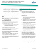
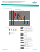
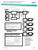
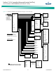
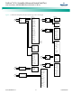
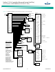
Figure 9. Local Menu Flow Diagrams (cont’d from previous page, cont’d on next page)
Status
Active Alarms
Power System
Rectifier
Battery
DC
AC
EIB
SMDU
Converter
SMDUP
SMTemp
Alarm History
Sys Inventory
E S C
A
E N T
Active Alarms
Minor: 0
Major: 0
Critical: 2
System Voltage
54.0 V
System Load
0.0 A
Mtnc Run Time
1.3 h
Alarm Status
No Alm
Power Split
Master
IB2 T2
21 deg. C
...
SMTemp1 T1
21 deg. C
DC Voltage
53.8 V
DC Current
8.5 A
Temperature
30 deg. C
DC Status
On
AC On/Off
On
Rated Current
35 A
Walk-In
Disabled
Rectifier ID
1
Rect Phase
A
Rectifier SN
010700213
Running Time
200 h
AC Voltage
224 V
Rectifier
Rect Group
Rect #1
Rect #2
1 RectAC
Mains Failure
081104 8:00:12
Critical
2 Power System
CAN Comm Fail
081104 8:05:02
Critical
DC Voltage
54.0 V
Total Load Current
0.0 A
Load Current
0.0 A
SYS Inventory
ACU+
Rect #1
Rect #2
EIB 1
IB 1
SMDUP 1
Conv #1
Conv #2
SMTemp 1
ENT
ENT
ENT
ENT
ENT
ENT
ESC
ESC
ESC
ESC
ESC
ESC
ESC
ESC
ESC
ENT
ENT
ENT
ESC
ESC
EN T
EN T
ESC
EN T
ESC
ENT
ENT
Press or
to cycle through
list of alarms.
Press ESC to return
to STATUS menu.
Press or
to cycle through
list of alarms.
ENT
ESC
1 IB2
DI3 Alarm
100629 12:18:35
100629 12:19:52
Device Name
ACU+
Part Number
M820D
Product Ver
001
SW Version
2.25
Serial Number
21024402512
ENT
ESC
ENT
ESC
Power System
DC
Alarm History
Minor: 0
Major: 0
Critical: 1
Press or
to move cursor in
STATUS screen.
Press ENT to enter
selected sub-menu.
To View Parameters:
Press or to move up and
down list of parameters.
To Select a Sub-Menu:
Press or to move cursor in
menu screen (selects menu item).
Press ENT to enter selected sub-menu.
Note:
For a complete list of alarms that can be displayed
in the STATUS Active Alarm menus, see the table
titled “Available Alarms” in the Operation Chapter.
A3
ESC
A2
A5
A6
Average Voltage
52.0 V
Total Current
0.2 A
Number of Rects
2
Num Rects Comm
2
Sys Cap Used
0.9 %
Max Cap Used
3.4 %
Min Cap Used
0.0 %
Rated Voltage
52.0 V
AC Phases
Single Phase
Max Curr Limit
462.2 A
Total Rated Cur
382.0 A
Rect Group
Battery
AC
EIB
ESC
A4
SMDU
Converter
Similar information
is displayed for each
device in the system.
SMDUP
A7
SMTemp
Rect #1
A1
EN T
ESC
Temp.
Probes
set as
“ambient”
show up
here.