
Brochures and Data Sheets

NetSure
™
ACU+ Controller (Advanced Control Unit Plus)
User Instructions, UM1M820BNA (Issue AK, March 3, 2014)
Spec. No: 1M820BNA, 1M820DNA Code: UM1M820BNA
Model No: M820B, M820D Issue AK, March 3, 2014
73
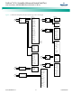
Note 4:
There shall be only one battery return reference (BRR) cable
for the two power systems. If the cable is appropriately sized
on the parallel power system, keep it as the BRR for both
power systems. If the cable is not appropriately sized on the
parallel power system, install a new BRR cable and connect it
preferably to the ACU+ power system since the parallel
power system may eventually be phased out.
Note 5:
If battery disconnect units (BDUs) are used on the new or
parallel power system, these shall be wired in such a way as
to be all triggered simultaneously in order to prevent any
overloading of these.
Note 6:
For the size and number of bridge cables between the two
power systems, take into consideration the voltage drop, the
available connecting points in each system, as well as the
fact that these cables are unfused and shall therefore be run
on a dedicated cable rack. “C” or “H” taps may be used to
make full use of available connecting points.
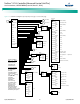
Note 7:
The legacy system retains the function of its controller and
the percent of load on each plant is controlled by the ACU+.
Alarms may be sent individually from each plant, or
combined using an ACU+ Interface Board and the
programmable relays resident in the controller.
Note 8:
Add a label on both power systems to indicate that these are
operating in the Power Split Mode with each other.
•
Optional Function Connections:
The following signals
from the existing system must be connected to digital
inputs of the ACU+ system interface board for these
functions to be active: Equalize Charge in Progress,
Battery Test in Progress, Load LVD Active, and Battery
LVD Active. Otherwise disable these functions.
Programming the ACU+ Power Split Feature
After an ACU+ power system has been connected to an existing
power system and both systems set for the same float voltage, you
will have to configure the Power Split parameters in the ACU+.
PROCEDURE
1. Set the Power Split mode to slave. Navigate to Main
Menu / Settings / Power System / General / Contactor
Mode. Set this parameter to “Slave Control”.
2. Reboot the ACU+ by pressing ESC and ENT at the same
time.
3. Navigate to Main Menu / Settings / Power System / Power
Split.
4. Navigate to and set the “Slave Current Limit” to a value
that will force the ACU+ system’s rectifiers to operate in
current limiting mode.
Note:
The Slave Current Limit must be set lower than the total
distribution current from the two plants. The default value is
60% of the ACU+ power system’s rectifier capacity.
5. Navigate to and set the “Delta Voltage”. This voltage is
by default set to 0.5V but can be readjusted.
• If the distribution current is lower than 50% of
the total capacity of the ACU+ power system,
the “Delta Voltage” can be adjusted to a lower
level than 0.5V to get a system voltage that is
closer to the desired float charging voltage.
• If the voltage drop between the existing system
and the ACU+ system is expected to be >0.5V,
the “Delta Voltage” can be adjusted to a higher
level than 0.5 V to get a correct split function.
• Temperature controlled battery charging
cannot be set in the ACU+ power system in
power split mode. If this function is
implemented in the existing power system, a
limited function within a temperature range of
approximately ±15°C will be achieved if the
Delta Voltage is set to a higher level, maximum
2.00V.
• If the “Delta Voltage” 0.5V is considered to be
too high, the split function can be tested at
various modes of operation to find a lower
setting.
Optional Function Setup
EQUALIZE CHARGE SETUP
If the equalize charge function is to be used, equalize charge must
be implemented in the existing power system and an equalizing
signal from its control unit must be connected to the ACU+.
1. Navigate to Main Menu / Settings / Battery / Charge / EQ
Voltage. Set the “EQ Voltage” to the same value as the
equalize voltage of the existing power system.
2. Using the Web Interface (Maintenance / Edit PowerSplit),
select the ACU+ digital input connected to the existing
systems equalize control circuit.
Note:
Equalize charging is controlled by the existing power system
via an incoming digital signal. The system will remain at the
set equalize charge voltage level as long as this signal is active.
BATTERY TEST SETUP
If the battery test function is to be used, battery test must be
implemented in the existing power system and a test signal from
its control unit must be connected to the ACU+.