
Brochures and Data Sheets

NetSure
™
ACU+ Controller (Advanced Control Unit Plus)
User Instructions, UM1M820BNA (Issue AK, March 3, 2014)
Spec. No: 1M820BNA, 1M820DNA Code: UM1M820BNA
Model No: M820B, M820D Issue AK, March 3, 2014
72
Note:
The same type of batteries with an equal amount of cells and
the same charging voltages must be used for both systems.
• The float voltage, equalize voltage, and battery test
voltage of the ACU+ power system must be set to the
same levels as that of the existing power system.
• The remote sense, if available and connected, of both the
ACU+ power system and existing power system must be
connected to the same point.
• If batteries are used, they must be of the same type.
• All the functions specific to the existing power system
and ACU+ power system and which depend on the
voltage or which act on the voltage must be disabled
from the existing power system and ACU+ power system.
This includes the following…
a. any equalization function,
b. any temperature compensation function,
c. any charge control function,
d. any battery discharge test function, and
e. any invalid current alarm.
In lieu of this, if battery charging and battery test functions are
implemented in the existing power system, they can remain if
signals for starting are connected from the control system of the
existing system to the ACU+ system.
Paralleling the Existing and ACU+ Power Systems
Admonishments
GENERAL SAFETY
Danger: YOU MUST FOLLOW APPROVED SAFETY PROCEDURES.
Performing the following procedures may expose you
to hazards. These procedures should be performed by
qualified technicians familiar with the hazards
associated with this type of equipment. These hazards
may include shock, energy, and/or burns. To avoid
these hazards:
a) The tasks should be performed in the order indicated.
b) Remove watches, rings, and other jewelry.
c) Prior to contacting any uninsulated surface or
termination, use a voltmeter to verify that no voltage
or the expected voltage is present.
d) Wear eye protection, and use recommended tools.
e) Use double insulated tools appropriately rated for the
work to be performed.
AC INPUT VOLTAGES
Danger: This system operates from AC voltage capable of
producing fatal electrical shock.
DC INPUT/OUTPUT VOLTAGES
Danger: Connecting the ACU+ power system to an existing power
system for “Power Split” mode involves working on live
equipment carrying live loads. This system produces DC
power and may require battery to be connected to it.
Although the DC voltage is not hazardously high, the
rectifiers and/or battery can deliver large amounts of
current. Exercise extreme caution not to inadvertently
contact or have any tool inadvertently contact a battery
terminal or exposed wire connected to a battery terminal.
NEVER allow a metal object, such as a tool, to contact
more than one termination at a time, or to simultaneously
contact a termination and a grounded object. Even a
momentary short circuit can cause explosion and injury.
Remove watches, rings, or other jewelry before connecting
leads. Cover any live busbars with a canvas sheet to
prevent short circuits caused by falling tools or parts.
Preparing the Existing and ACU+ Power Systems
• Install and turn-up the ACU+ power system as describe in
the installation instructions furnished with the power
system.
• Set the float voltage on both the existing and ACU+
power systems to the same level. Temperature
compensation functionality, if used, should be disabled
on both power systems.
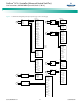
Paralleling the Systems
• Connect the Battery and Battery Return busbars of the
ACU+ Power System to the main charge busbars (rectifier
side of the shunt) on the parallel power system. Size the
cable for the largest current between systems.
Note 1:
The connections between the two power systems should be
done with power cables appropriately sized to be capable of
carrying the maximum current that can circulate between
the two power systems.
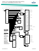
Note 2:
If the parallel power system incorporates a main plant shunt,
the connections of the cables from the ACU+ power system
to the parallel power system shall be made on the main
charge busbars (rectifier side of the shunt).
Note 3:
To compensate for voltage drop, it is recommended to
connect the ACU+ power system’s remote sense leads (if
available) to the same point of sensing as the parallel power
system.