
Brochures and Data Sheets

NetSure
™
ACU+ Controller (Advanced Control Unit Plus)
User Instructions, UM1M820BNA (Issue AK, March 3, 2014)
Spec. No: 1M820BNA, 1M820DNA Code: UM1M820BNA
Model No: M820B, M820D Issue AK, March 3, 2014
71
Power Split Feature
In Power Split applications, the output of the power system
controlled by the ACU+ can be connected in parallel with an
existing power system. Each system is controlled independently
via its own Controller. The ACU+ power system is referred to as the
"slave" system and the existing power system as the "master"
system. The Power Split feature controls the ACU+ power system’s
output voltage and rectifiers' current limit so that the "slave" power
system shares the load with the "master" system.
Optional Functions: The ACU+ Controller can mimic the equalize
and battery test functions of the “master” system’s Controller. In
addition, the ACU+ Controller can mimic the low voltage load
disconnect and/or low voltage battery disconnect functions of the
“master” system. This is accomplished by supplying digital signals
from the “master” system’s Controller to the ACU+. This allows
these functions to remain active in the “master” system.
Overview
See “Power Split Feature” on page 6.
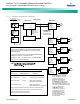
How Power Split Works
There are four User adjustable parameters for Power Split. They
are:
•
Slave Curr Lmt:
Current limit point for power system
designated as the slave system in a "Power Split"
configuration.
•
Delta Volt:
The offset voltage that the power system
designated as the slave system in a "Power Split"
configuration is set to. It is suggested to leave this value
at the default (0.5 volts).
•
Proportion Coeff:
The proportional coefficient that the
power system designated as the slave system in a "Power
Split" configuration is set to. It is suggested to leave this
value at the default (30%).
•
Integral Time:
The integral time that the power system
designated as the slave system in a "Power Split"
configuration is set to. It is suggested to leave this value
at the default (60 seconds).
The ACU+ Controller uses these parameters to control the load
sharing operation between the two power systems.
Depending on the systems’ configurations, their rectifier
capacities, their distribution load capacities, and the Power Split
configuration; four operating modes can occur.
Low Load Operation
When the total load current demand is lower than the SLAVE
CURRENT LIMIT value, the ACU+ power system voltage will be
increased by the programmed DELTA VOLTAGE setting forcing the
ACU+ power system to carry the load. Make sure that the output
voltage does not exceed the battery float range recommended by
the manufacturer. In this operating mode, no current will be
delivered by the existing power system.
Normal Load Operation
When the total load current demand reaches the SLAVE CURRENT
LIMIT value, the ACU+ power system operates in output current
limit and its output voltage will be decreased (up to the DELTA
VOLTAGE setting) in order to regulate the current, allowing the
existing power system to deliver the remaining current. Both the
ACU+ power system and the existing power system are now
providing current to the load.
High Load Operation
If current demand increases and the existing power system
reaches its current limit setting, float voltage will again begin to
decrease. When the voltage falls below the float setting minus the
DELTA VOLTAGE setting, the ACU+ system will come out of current
limit and now deliver the additional current necessary to satisfy the
load. This operation may occur when the batteries are being
recharged, such as after a commercial AC failure.
Over Load Operation
If the load current is greater than the combined current capacities
of the ACU+ system and the existing power system, both power
systems will go into current limit. Both systems and the batteries
will feed the load. The output voltage will depend on the
conditions of the batteries. This operation occurs if the total
capacity of the rectifiers is too low in relation to the need for
increased current.
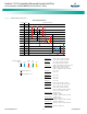
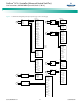
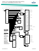
Operating Modes
Figure 5 illustrates the four modes of operation described above.
The Normal Load Operation is considered to be the normal mode.
In this mode both the ACU+ system and the existing parallel power
system are both delivering load current. This is main purpose of
using Power Split, to avoid putting the burden of delivering the
entire load onto one of the two power systems.
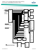
Requirements and Conditions
The two DC power systems must be connected in parallel as
described in “Paralleling the Existing and ACU+ Power Systems” on
page 72.
Before paralleling the two systems, the following conditions must
be met for proper Power Split function.
Note:
The control features of the combined system are limited to
those of the original power system.