
Brochures and Data Sheets


NetSure
™
ACU+ Controller (Advanced Control Unit Plus)
User Instructions, UM1M820BNA (Issue AK, March 3, 2014)
Spec. No: 1M820BNA, 1M820DNA Code: UM1M820BNA
Model No: M820B, M820D Issue AK, March 3, 2014
23
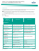
WEB Menu Navigation:
Device Information / SMDUP Group / SMDUP 1 / select the Settings
Tab and enter the following parameters.
Parameters
• Current1 Break Value (A) (Device rating.)
• Current1 High Current Limit (% of Current# Break Value.)
• Current1 Very High Current Limit (% of Current# Break
Value.)
• Shunt # Current (Rating of Shunt.)
• Shunt # Voltage (Rating of Shunt.)
Setting the Load Current Alarm
Local Menu Navigation:
Main Menu / Settings / Power System / General / Load Curr Alarm.
WEB Menu Navigation:
Device Information / Power System / Settings Tab / Load Current
Alarm.
Enter a value (in AMPS). If load current exceeds this value, a load
current alarm is issued.
Using the Relay Test Feature
Note:
The relay test can only be performed when no alarms are
present.
Automatic Test
When placed in Relay Automatic Test Mode, all relays on the IB2
board deenergize (when set for Fail Safe), then one-by-one each
relay energizes for the time period selected and then deenergizes.
If the system is equipped with an EIB board, after the IB2 relays are
tested, one-by-one each relay on the EIB board deenergizes for the
time period selected and then re-energizes. At the end of the test,
all relays are returned to their normal state (if no alarms are
present).
Local Menu Navigation:
Main Menu / Settings / Power System / General / set the Relay Test
Time.
then
Main Menu / Settings / Power System / General / Relay Test / set to
Automatic.
Note:
The relay test can be exited at any time by setting the Relay
Test to Disabled.
WEB Menu Navigation:
Device Information / Power System / Settings Tab / set the Relay
Test Time.
then
Device Information / Power System / Settings Tab / Relay Test / set
to Automatic.
Note:
The relay test can be exited at any time by setting the Relay
Test to Disabled.
Individual Test
When placed in Relay Individual Test Mode, relays can be tested
individually. This is the same procedure as “Manually Forcing
Relays” on page 26 except you do not place the Controller in
Manual Mode.
Local Menu Navigation:
Main Menu / Settings / Power System / General / Relay Test / set to
Individual.
then
Main Menu / Manual / Power System / Relay Output [number]
(individually you can set the state of the relays on the IB2 Board).
Main Menu / Manual / EIB / EIB1 / Relay Output [number]
(individually you can set the state of the relays on the EIB Board).
• Select the other state for an alarm relay (active / not
active).
• After confirming the change, the alarm relay will
momentarily toggle to the chosen state. The alarm relay
then reverts back to being controlled by the ACU+.
• When done, set “Relay Test” to “Disabled”. Note that if
there is no User interaction for 10 minutes, the Relay Test
will automatically revert to the “disabled” state.
WEB Menu Navigation:
Device Information / Power System / Settings Tab / Relay Test / set
to Individual.
then
Device Information / Power System / Control Tab (individually you
can set the state of the relays on the IB2 Board).
Device Information / EIB Group / EIB 1 / Control Tab (individually
you can set the state of the relays on the EIB Board).
The Control Tab allows you to change the state of an alarm relay.
• In the "Set value" box, select the other state for an alarm
relay (active / not active).
• Click on "set".
• After confirming the change, the alarm relay will
momentarily toggle to the chosen state. The alarm relay
then reverts back to being controlled by the ACU+.
• When done, set “Relay Test” to “Disabled”.