
Brochures and Data Sheets


NetSure
™
ACU+ Controller (Advanced Control Unit Plus)
User Instructions, UM1M820BNA (Issue AK, March 3, 2014)
Spec. No: 1M820BNA, 1M820DNA Code: UM1M820BNA
Model No: M820B, M820D Issue AK, March 3, 2014
20
Setting Battery Charge Temperature Compensation
The following need to be set for the Battery Charge Temperature
Compensation feature.
See above for selecting the battery temperature compensation
temperature sensor; or select maximum, average, or Average
SMBRC.
Local Menu Navigation:
Main Menu / Settings / Battery / Temp Comp.
Enter values for the following parameters:
Temp CompCenter, Temp Comp Coeff, TempComp Sensor, Comp
Temp High2, Comp Temp High1, Comp Temp Low, Temp Comp
Max V, Temp Comp Clamp, and Temp Comp Min V (note that you
have to enable Temp Comp Clamp to set the Temp Comp Max V
and Min V values).
WEB Menu Navigation:
Quick Settings / Temp Compensation Setting.
Enter values for the following parameters:
Temperature Compensation Center, Temp Comp Coefficient
(slope), Temp Compensation Probe Number, Comp Temp High2,
Comp Temp High1, Comp Temp Low, Temp Comp Voltage Clamp,
Temp Comp Max Voltage, and Temp Comp Min Voltage (note that
you have to enable Temp Comp Clamp to set the Temp Comp Max
V and Min V values).
Setting Rectifier High Voltage Shutdown
Local Menu Navigation:
Main Menu / Settings / Rectifier / All Rect Set / HVSD (enabled),
then
Main Menu / Settings / Rectifier / All Rect Set / HVSD Limit
WEB Menu Navigation:
Device Information / Rectifier Group / Settings Tab / HVSD
(enabled), then
Device Information / Rectifier Group / Settings Tab / HVSD Limit.
Setting Rectifier Current Limit
Local Menu Navigation:
Main Menu / Settings / Rectifier / All Rect Set / Current Limit
(enabled), then
Main Menu / Settings / Rectifier / All Rect Set / Current Limit Pt
WEB Menu Navigation:
Device Information / Rectifier Group / Settings Tab / Current Limit
(enabled), then
Device Information / Rectifier Group / Settings Tab / Current Limit
Point.
Setting Over Voltage Alarm 1
Local Menu Navigation:
Main Menu / Settings / Power System / General / Over Voltage 1.
WEB Menu Navigation:
Device Information / Power System Group / Settings Tab / Over
Voltage 1.
Setting Over Voltage Alarm 2
Local Menu Navigation:
Main Menu / Settings / Power System / General / Over Voltage 2
WEB Menu Navigation:
Device Information / Power System Group / Settings Tab / Over
Voltage 2.
Setting Under Voltage Alarm 1
Local Menu Navigation:
Main Menu / Settings / Power System / General / Under Voltage 1.
WEB Menu Navigation:
Device Information / Power System Group / Settings Tab / Under
Voltage 1.
Setting Under Voltage Alarm 2
Local Menu Navigation:
Main Menu / Settings / Power System / General / Under Voltage 2.
WEB Menu Navigation:
Device Information / Power System Group / Settings Tab / Over
Voltage 2.
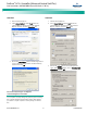
Configuring the ACU+ Identification of Rectifiers and
Assigning which Input Phase is Connected to the Rectifiers
When rectifiers are all installed prior to applying power and
starting the system, the order in which the ACU+ identifies the
rectifiers is by serial number (lowest serial number is Rect 1, next
lowest is Rect 2, etc.). If you prefer the ACU+ to identify the
rectifiers by position in the system, perform the following
procedure.
Upon power up, the ACU+ arbitrarily assigns Phase A, B, or C to
each rectifier. This assignment is used to display rectifier AC input
phase voltage(s). The User may reassign the phase to each rectifier
per your specific installation by following the procedure below.