
Brochures and Data Sheets


NetSure
™
ACU+ Controller (Advanced Control Unit Plus)
User Instructions, UM1M820BNA (Issue AK, March 3, 2014)
Spec. No: 1M820BNA, 1M820DNA Code: UM1M820BNA
Model No: M820B, M820D Issue AK, March 3, 2014
19
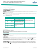
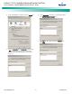
Setting Battery Capacity Parameters
Local Menu Navigation:
Main Menu / Settings / Battery / Battery # / Rated Capacity.
WEB Menu Navigation:
Device Information / Battery Group / Battery # / select the Settings
Tab and enter the Battery Rating parameter.
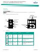
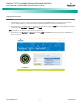
Setting Temperature Sensors
Temperature sensors may be connected to the…
• Temp1 and Temp2 ports on an IB2 Interface Board,
• Temp1 and Temp2 ports on an EIB Interface Board, and
• Temp1 through Temp8 ports of up to eight (8) SM-Temp
modules.
Each port (sensor) may be set as None, Battery, or Ambient.
A temperature sensor set as an ambient temperature sensor may
also be set as the sensor which displays the ambient temperature
on the Web Interface’s Homepage.
A temperature sensor set as a battery temperature sensor may
also be set as the temperature compensation sensor (in addition,
the temperature compensation sensor is the sensor which displays
the battery temperature on the Web Interface’s Homepage).
A temperature sensor set as a battery temperature sensor may
also be set as the BTRM (Battery Thermal Runaway Management)
sensor (in addition, the BTRM sensor is the sensor which is used for
the High Temperature Disconnect [HTD] Feature.)
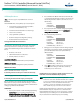
• First, set each temperature sensor in the system to None,
Battery, or Ambient.
Local Menu Navigation:
Main Menu / Settings / Power System / General / IB2
Temp#.
Main Menu / Settings / Power System / General / EIB
Temp#.
Main Menu / Settings / SMTemp / SMTemp # / T# Assign
Equip.
WEB Menu Navigation:
Device Information / Power System / Settings Tab / IB2
Temp #.
Device Information / Power System / Settings Tab / EIB
Temp #.
Device Information / SM Temp Group / SM Temp # /
Settings Tab / Temperature# Assign Equipment.
Note:
Also set High2, High1, and Low temperature alarms
for each temperature sensor (from the Web
Interface). Note that you cannot set high and low
temperature alarms for individual temperature
sensors from the Local Menus. High and low
temperature alarm settings for the temperature
sensors set as ambient are found in the Device
Information / Power System / Settings tab. High and
low temperature alarm settings for the probes set as
battery are found in the Device Information / Battery
Group / Settings tab.
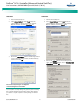
• Second, if desired, set a temperature sensor set as an
ambient temperature sensor as the sensor which displays
the ambient temperature on the Web Interface’s
Homepage. Then set High2, High1, and Low ambient
temperature alarms (from the same menu).
Local Menu Navigation:
Main Menu / Settings / Power System / Amb Temp
Sensor.
WEB Menu Navigation:
Device Information / Power System / Settings Tab /
Ambient Temp Sensor.
• Third, if desired, set a temperature sensor set as a battery
temperature sensor as the battery temperature
compensation sensor. Then set High2, High1, and Low
compensation temperature alarms (from the same
menu).
Local Menu Navigation:
Main Menu / Settings / Battery / Temp Comp /
TempComp Sensor.
WEB Menu Navigation:
Device Information / Battery Group / Settings Tab / Temp
Compensation Probe Number.
• Fourth, if desired, set a temperature sensor set as a
battery temperature sensor as the BTRM sensor. Then set
High2 and High1 BTRM temperature alarms (from the
same menu). If battery temperature exceeds the “BTRM
Temp High2” setting, system voltage is lowered to the
BTRM voltage setting (set from the same menu). Note,
you must first enable this feature (from the same menu).
Local Menu Navigation:
Main Menu / Settings / Battery / Basic / BTRM
TempSensor.
WEB Menu Navigation:
Device Information / Battery Group / Settings Tab / BTRM
Temp Sensor.