
Brochures and Data Sheets


NetSure
™
ACU+ Controller (Advanced Control Unit Plus)
User Instructions, UM1M820BNA (Issue AK, March 3, 2014)
Spec. No: 1M820BNA, 1M820DNA Code: UM1M820BNA
Model No: M820B, M820D Issue AK, March 3, 2014
14
WEB Interface Access
Note:
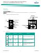
The ACU+ supports a 10/100M Ethernet connection.
Overview
Via the WEB Interface, a User (with proper access level) can:
• View real-time operating information (rectifiers,
converters, AC, DC, Batteries, etc.).
• View and download information recorded in logs.
• Send control commands.
• Set programmable parameters.
• Download and upload configuration package.
• Download firmware to the Controller.
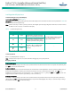
Setting IP Communications Parameters
The Controller’s IP parameters (IP, subnet mask, and gateway
addresses) must be set to match your company’s network
settings. The default settings for these parameters are shown
below.
• IP Address: 192.168.1.2
• Subnet Mask Address: 255.255.255.0
• Gateway Address: 192.168.1.1
Local Menu Navigation:
Main Menu / Settings / Communication / enter parameters.
WEB Menu Navigation:
Maintenance / Network Configuration / enter parameters.
WEB Interface Menus
Refer to “WEB Interface Menus” on page 102.
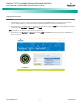
Connecting to the Controller (over a network connection)
Refer to Logging into the Controller on page 17.
Connecting the Controller Directly to your Computer
Before connecting your computer directly to the Controller’s
Ethernet Port, record your current network settings as outlined
below, then change these settings to match the communications
settings programmed in the Controller.
PROCEDURE
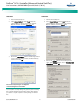
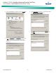
1. Record your computer’s network settings by launching
Control Panel
in your computer. Navigate through
Network Connections Local Area Connection
Properties Internet Protocol (TCP/IP) Properties
.
2. Record whether the "Obtain an IP address automatically"
or "Use the following IP address" button is selected. If "Use
the following IP address" button is selected, also record
the following:
IP Address:
Subnet Mask:
Default Gateway:
3. Record your Controller’s network settings by navigating
the Controller’s local display panel to
Main Menu
Settings Communication
.
4. Record the following information:
IP Address:
Subnet Mask:
Default Gateway:
Example:
IP Address: 192.168.1.2
Subnet Mask: 255.255.255.0
Default Gateway: 192.168.1.1
5. Change your local computer’s network settings using the
information you acquired in Step 4), except that the last
part of the IP address needs to be replaced with any
different number.
IP Address:
Subnet Mask:
Default Gateway:
Example:
IP Address: 192.168.1.3
Subnet Mask: 255.255.255.0
Default Gateway: 192.168.1.1
6. Select
OK
. Note that you may have to reboot your local
computer for the settings to take effect. Follow any
instruction you see on the screen.
Disabling Proxy Server Settings to Enable a Connection to the
Controller over an Intranet Network (if required)
Note:
This procedure needs to be performed only when the
Controller is connected to an Intranet and the User’s computer
is set to access the Intranet through a proxy server. Note that if
the Controller is connected to the Internet and the User’s
computer is connected to an Intranet, the User may not be
able to disable the proxy server and access the Controller.
If the Controller’s Ethernet Port is connected to your company’s
Intranet Network and your computer is also connected to the
Intranet Network but requires access via a proxy server, you must
disable the proxy server settings to access the Controller. Follow
the procedure below to disable the proxy server settings.