
Brochures and Data Sheets

NetSure
™
ACU+ Controller (Advanced Control Unit Plus)
User Instructions, UM1M820BNA (Issue AK, March 3, 2014)
Spec. No: 1M820BNA, 1M820DNA Code: UM1M820BNA
Model No: M820B, M820D Issue AK, March 3, 2014
154
Replacement Procedures
ACU+ Controller Replacement
DANGER! Follow all “Important Safety Instructions”
found in the documentation provided with the system
the ACU+ Controller is installed in.
WARNING! ACU+ CONTROLLER HANDLING.
Installation or removal of the ACU+ Controller requires
careful handling. To avoid possibility of ACU+ Controller
damage from static discharge, a static wrist strap
grounded through a one megohm resistor should always
be worn when handling the ACU+ Controller. ESD-
protective packaging material must also be used when
carrying/shipping the ACU+ Controller.
Note:
Depending on your network security settings, when you
remove a device that is connected to your network and assign
the same IP address to the replacement device, you may not be
allowed to communicate with the replacement device over the
network. Contact your network administrator for assistance.
The ACU+ Controller is hot swappable. It can be removed and
installed with the system operating and without affecting the
output bus.
PROCEDURE
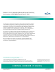
1. Before performing this procedure, ensure the
replacement ACU+ Controller contains the same
configuration package as the existing ACU+ Controller.
Refer to the Configuration Label on the side of the
replacement ACU+ Controller for the Configuration Part
Number. If the existing Controller is operational, navigate
the menus to view its configuration package (MAIN
SCREEN/ESC/ENT/ENT).
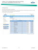
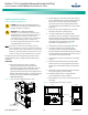
Figure 10. ACU+ Controller Configuration Label Location
2. Performing this procedure may activate external alarms.
Do one of the following. If possible, disable these alarms.
If these alarms cannot be easily disabled, notify the
appropriate personnel to disregard any future alarms
associated with this system while this procedure is being
performed.
3. Connect an approved grounding strap to your wrist.
Attach the other end to a suitable ground.
4. Loosen the captive fastener securing the latch
mechanism to the front of the ACU+ Controller. Pull the
latch mechanism away from the ACU+ Controller (this
will retract the latch mechanism located on the bottom
of the ACU+ Controller). This unlocks the ACU+
Controller from the shelf. Refer to Figure 11.
5. Slide the ACU+ Controller completely from the shelf.
6. Loosen the captive fastener securing the latch
mechanism to the front of the replacement ACU+
Controller. Pull the latch mechanism away from the ACU+
Controller (this will retract the latch mechanism located
on the bottom of the ACU+ Controller).
7. Slide the ACU+ Controller completely into its mounting
position.
8. Push the latch mechanism into the front panel of the
ACU+ Controller, and secure by tightening the captive
fastener. This locks the ACU+ Controller securely to the
shelf.
9. Wait for the Controller to finish booting and verify that
the complete system operates normally.
10. Enable the external alarms, or notify appropriate
personnel that this procedure is finished.
11. Ensure that there are no local or remote alarms active on
the system.
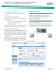
Figure 11. Latch Mechanism on the ACU+ Controller
C o n fig u ration File
Pa rt N um b e r Labe l
M820D
M820B
Captive Fastener
Latch Mechanism
ESC
ENT
M820D M820B
Danger
Warning