
Brochures and Data Sheets

NetSure
™
ACU+ Controller (Advanced Control Unit Plus)
User Instructions, UM1M820BNA (Issue AK, March 3, 2014)
Spec. No: 1M820BNA, 1M820DNA Code: UM1M820BNA
Model No: M820B, M820D Issue AK, March 3, 2014
146
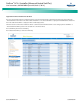
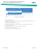
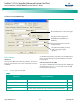
Column Descriptions
•
Operator:
The Operator column selects the type of function that will be performed. The list of Operators is shown in
the Symbol Information table (from line 3 and down) in the previous PLC screen.
•
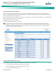
Input 1:
The Input 1 column is divided into the following three sub-columns.
a)
EquipName/Register:
This column shows the Equipment that the signal to be selected in c) below is associated
with. (Equipment is not necessarily connected to a physical device. An Equipment can be connected to several
physical devices and vice versa.)
The Equipment can be replaced by a Register. Every Register is given a unique number between 0 and 99. A
Register works as a temporary storage place that will be cleared after every run of the PLC function.
b)
Signal Type:
This column shows the type of signal to be selected in c) below.
The ACU+ has four different signal types:
• Sample (measured or calculated values, status).
• Control (control of different functions or events).
• Setting (different kind of settings).
• Alarm (alarms, these signals will only be activated if the alarm category is set to anything else than NA).
c)
Signal Name:
You select the signal from this column. Signals that are shown in the drop-down list box are based
on your selections in a) and b) above.
•
Input 2:
(See Input 1 above.)
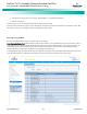
•
Param 1:
This column shows if any parameter is used.
A parameter is just a way to enter a value, which can be used in compares with signals.
•
Param 2:
(See Param 1 above.)
•
Output:
The Output column is divided in three sub-columns, which has the same information as for the Inputs.
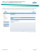
2. Choose the type of Operator. The web page will disable some boxes that are not applicable for the type of Operator.