
Brochures and Data Sheets

NetSure
™
ACU+ Controller (Advanced Control Unit Plus)
User Instructions, UM1M820BNA (Issue AK, March 3, 2014)
Spec. No: 1M820BNA, 1M820DNA Code: UM1M820BNA
Model No: M820B, M820D Issue AK, March 3, 2014
5
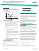
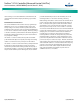
Functional Description:
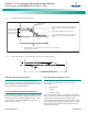
For manual battery discharge tests as well
as for cyclic battery discharge tests, the following parameters must
be set: End Voltage, Test Time, and Battery Capacity Discharge
Limit. See Figure 4.
Figure 4. Battery Test Diagram
BATTERY DISCHARGE TEST SEQUENCE:
• In time test modes, the output voltage of the rectifiers is
reduced so that only the batteries power the load. If the
batteries fail, the rectifiers power the load.
• In stable current test mode, the output voltage of the
rectifiers is reduced so that the batteries supply the
preset test current to the load.
• The battery test continues until one of the following
occurs:
a. The preset test time, see Figure 4, expires. The
battery has passed the test.
b. The battery voltage drops below the preset end
voltage level (V
end
) (Figure 4). The battery has not
passed the test and the test is interrupted. A battery
test alarm is activated.
c. The battery capacity drops below the preset test end
battery capacity. The battery has not passed the test
and the test is interrupted. A battery test alarm is
activated.
• After the battery discharge test, the output voltage of
the rectifiers increase so that the rectifiers supply the
system and charge the batteries.
Battery LVD (Low Voltage Disconnect)
To prevent serious damage to the batteries during a commercial
AC power failure, the batteries can be disconnected by voltage or
time control.
The batteries are reconnected automatically when commercial AC
power is restored and a predetermined DC voltage level is reached.
•
Voltage Controlled Disconnection:
When the set voltage
level is reached, the batteries are disconnected.
•
Time Controlled Disconnection:
When the set time has
elapsed, the batteries are disconnected.
Battery Capacity Prediction
The ACU+ can predict battery capacity.
Battery Block and Battery Midpoint Monitoring
The ACU+ can monitor battery blocks (12V blocks) or midpoint
battery voltage of battery strings connected to the EIB assembly.
An alarm is issued when either battery block voltage or battery
midpoint voltage is abnormal.
Enhanced Battery Monitoring with SM-BRC
When connected to an SM-BRC, the ACU+ provides enhanced
battery monitoring.
Thermal Runaway Detection and Management
Functional Description:
The system uses several control
mechanisms to avoid thermal runaway.
First: During a short high rate discharge, the batteries will normally
get hot. The ACU+ takes this into consideration. After completion
of the discharge duty, the batteries are recharged with a limited
current to avoid heating the batteries any further.
Second: The temperature of the batteries can be monitored, and
the ACU+ sets the charge voltage appropriately, as previously
described under Battery Charge Temperature Compensation.
Third: In addition to battery temperature compensation, if battery
temperature rises above a set temperature limit, the system stops
battery charging completely by lowering the output voltage to the
“BTRM Voltage” setting. This allows the batteries to cool down.
The system also provides alarm notification of this occurrence.
Power supplied to customer equipment is not interrupted.
Fourth: The battery LVD circuits can be programmed to open
(disconnect) if a high temperature event occurs (HTD – High
Temperature Disconnect). The contactor(s) open when battery
temperature rises above a programmable value and close again
when battery temperature falls below another programmable
value.
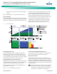
Intelligent Power Matching (Energy Optimization Mode)
With Energy Optimization Mode (ECO):
• The Controller monitors load current versus system
capacity.