
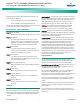
Brochures and Data Sheets

NetSure
™
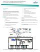
ACU+ Controller (Advanced Control Unit Plus)
User Instructions, UM1M820BNA (Issue AK, March 3, 2014)
Spec. No: 1M820BNA, 1M820DNA Code: UM1M820BNA
Model No: M820B, M820D Issue AK, March 3, 2014
2
Function Descriptions
Rectifier Control
Rectifiers are automatically controlled by the ACU+ Controller. The
ACU+ Controller provides an Energy Optimization Mode function.
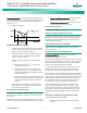
Energy Optimization permits an installation to only operate
rectifiers as needed to maintain the load and keep batteries in a
fully charged condition. As load increases, Energy Optimization
turns on additional rectifiers as needed to maintain the load. As
load decreases, Energy Optimization places rectifiers in standby to
conserve energy usage. Rectifiers which are always operating to
maintain any load requirements are cycled through the group of
rectifiers controlled by this feature to provide uniform operating
times for each rectifier.
Converter Control
Converters are automatically controlled by the ACU+ Controller.
System Components Monitoring and
System Alarms Generation
The ACU+ Controller monitors the components comprising the
system (such as the rectifiers, converters, and supervisory
modules) and generates alarms if a fault condition occurs. The
ACU+ Controller also maintains an alarm history log.
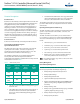
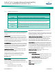
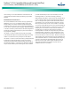
The available system alarms are programmed with an Alarm
Severity Level. Each Alarm Severity Level has different
visual/audible alarm attributes. Available Alarm Severity Levels and
their attributes are listed in Table 1.
Table 1. Alarm Severity Levels
Alarm
Severity
Level
ACU+ Red
Alarm
Indicator
ACU+ Yellow
Alarm
Indicator
ACU+
Audible
Alarm
Critical Alarm
(CA)
ON OFF ON
Major Alarm
(MJ)
ON OFF ON
Minor Alarm
(MN)
OFF ON OFF
No Alarm
OFF
OFF
OFF
• The alarm indicator turns OFF if the fault(s) that triggered
the alarm clears.
• The audible alarm can be silenced by pressing any key on
the ACU+ Controller local interface pad. The audible
alarm is also silenced if the fault(s) that triggered the
alarm clears.
• An audible alarm cutoff feature can be programmed that
silences the audible alarm after a pre-set programmable
time period. The audible alarm can also be disabled.
The available system alarms can also be mapped to alarm relays
(located on ACU+ interface boards) that can be wired to external
alarm circuits.
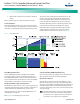
Operating Data Acquisition and Data Logs
The ACU+ Controller acquires and analyses real time data from the
system’s components such as the rectifiers, converters, and
supervisory modules.
The ACU+ Controller uses this data to process alarms and also
records data in logs. The logs are viewed using the WEB Interface
and consist of the following. Logs can be saved in the text (.txt)
format.
• Alarm History Log: records 600 latest alarms.
• Data History Log: records 60000 latest history data.
• Control Log: records 500 latest control events.
• System Log: records 3000 latest system events.
• Diesel Test Log: records 500 latest diesel test results.
• Battery Test Log: up to twelve (12) battery discharge
tests can be performed and recorded per year.
Note:
Once maximum number of log entries is reached, new entries
overwrite oldest entries.
Battery Management
General Battery Management
The ACU+ Controller provides the following battery management
functions (except Lithium Ion Battery Configuration).
• Battery Charge Temperature Compensation
• Battery Equalize Charge
• Battery Charge Current Limit
• High and Low Battery Temperature Alarms
• Battery Thermal Runaway Management (BTRM) Feature
(Reduces Voltage during a High Battery Temperature
Condition)
• Battery Discharge Tests
• Battery Test Logs (maximum twelve [12] logs, maximum
eighteen [18] battery strings per log)
• Battery LVD (Low Voltage Disconnect)
• Battery Capacity Prediction