NetSure™ ACU+ Controller (Advanced Control Unit Plus) User Instructions, UM1M820BNA (Issue AK, March 3, 2014) Specification Number: 1M820BNA, 1M820DNA Model Number: M820B, M820D Model M820B Model M820D
NetSure™ ACU+ Controller (Advanced Control Unit Plus) User Instructions, UM1M820BNA (Issue AK, March 3, 2014) This page is intentionally blank. Spec.
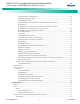
NetSure™ ACU+ Controller (Advanced Control Unit Plus) User Instructions, UM1M820BNA (Issue AK, March 3, 2014) Table of Contents Admonishments Used in this Document .............................................................................................................. vii Introduction ......................................................................................................................................................... 1 Preface .......................................................
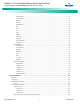
NetSure™ ACU+ Controller (Advanced Control Unit Plus) User Instructions, UM1M820BNA (Issue AK, March 3, 2014) Local Menu Navigation Keys and LCD Display .................................................................................................. 13 Local Display Menus ....................................................................................................................................... 13 Navigating the Menus ............................................................................
NetSure™ ACU+ Controller (Advanced Control Unit Plus) User Instructions, UM1M820BNA (Issue AK, March 3, 2014) Adding, Deleting, and Modifying Users ................................................................................................... 24 Assigning Severity Level to Alarms .......................................................................................................... 24 Assigning Relays to Alarms ........................................................................................
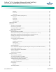
NetSure™ ACU+ Controller (Advanced Control Unit Plus) User Instructions, UM1M820BNA (Issue AK, March 3, 2014) Alarm Setting ......................................................................................................................................... 87 Power System ......................................................................................................................................... 87 Rectifier ..................................................................................
NetSure™ ACU+ Controller (Advanced Control Unit Plus) User Instructions, UM1M820BNA (Issue AK, March 3, 2014) Status Tab ............................................................................................................................................ 112 Control Tab .......................................................................................................................................... 113 Settings Tab .............................................................................
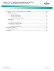
NetSure™ ACU+ Controller (Advanced Control Unit Plus) User Instructions, UM1M820BNA (Issue AK, March 3, 2014) Accessing the Controller via a Network Management System (NMS).................................................................. 149 General ............................................................................................................................................................... 149 NMS Supported by SNMP Agent ....................................................................
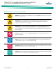
NetSure™ ACU+ Controller (Advanced Control Unit Plus) User Instructions, UM1M820BNA (Issue AK, March 3, 2014) Admonishments Used in this Document DANGER! Warns of a hazard the reader will be exposed to that will likely result in death or serious injury if not avoided. (ANSI, OSHA) Danger Warning Caution WARNING! Warns of a potential hazard the reader may be exposed to that could result in death or serious injury if not avoided.
NetSure™ ACU+ Controller (Advanced Control Unit Plus) User Instructions, UM1M820BNA (Issue AK, March 3, 2014) This page is intentionally blank. Spec.
NetSure™ ACU+ Controller (Advanced Control Unit Plus) User Instructions, UM1M820BNA (Issue AK, March 3, 2014) Introduction Preface These instructions describe the complete functionality of the ACU+ Controller. Some functionality is dependent on hardware connected to the ACU+ Controller. Your system may not utilize all the functionality described. Refer also to the ACU+ Configuration Drawing (C-drawing) furnished with your system for a list of factory default settings.
NetSure™ ACU+ Controller (Advanced Control Unit Plus) User Instructions, UM1M820BNA (Issue AK, March 3, 2014) Function Descriptions • Rectifier Control Rectifiers are automatically controlled by the ACU+ Controller. The ACU+ Controller provides an Energy Optimization Mode function. Energy Optimization permits an installation to only operate rectifiers as needed to maintain the load and keep batteries in a fully charged condition.
NetSure™ ACU+ Controller (Advanced Control Unit Plus) User Instructions, UM1M820BNA (Issue AK, March 3, 2014) • Battery Block and Battery Midpoint Monitoring • Enhanced Battery Monitoring with SM-BRC • Thermal Runaway Detection/Management To protect batteries and voltage-sensitive loads, compensation is automatically limited to a maximum of two volts (48V systems) or one volt (24 volt systems) above or below the nominal output level (float setting).
NetSure™ ACU+ Controller (Advanced Control Unit Plus) User Instructions, UM1M820BNA (Issue AK, March 3, 2014) Figure 2. Temperature Compensated Voltage Control V TempComp Coeff setting (mV/°C). 1V Max (24V System) 2V Max (48V System) 1V Max (24V System) 2V Max (48V System) Vhigh Upper voltage level where temperature compensation clamps the voltage. Limited to the TEMP COMP MAX V setting. Vnom Nominal voltage (voltage at nominal temperature).
NetSure™ ACU+ Controller (Advanced Control Unit Plus) User Instructions, UM1M820BNA (Issue AK, March 3, 2014) Functional Description: For manual battery discharge tests as well as for cyclic battery discharge tests, the following parameters must be set: End Voltage, Test Time, and Battery Capacity Discharge Limit. See Figure 4. Figure 4. Battery Test Diagram • Voltage Controlled Disconnection: When the set voltage level is reached, the batteries are disconnected.
NetSure™ ACU+ Controller (Advanced Control Unit Plus) User Instructions, UM1M820BNA (Issue AK, March 3, 2014) • The Controller commands some rectifiers to standby in rotation. Refer to “Rectifier Control” on page 2 for further description. Power Split Feature The Power Split feature allows you to connect the power system controlled via the ACU+ to an existing DC power system instead of extending or completely replacing the existing DC power system.
NetSure™ ACU+ Controller (Advanced Control Unit Plus) User Instructions, UM1M820BNA (Issue AK, March 3, 2014) Table 2. Available Logical Components Logical Component Logic NOT Logic OR Logic AND Description NOT; Returns the inverted value of the input signal/parameter. OR; Returns active (true) if any of the two signals/parameters are active (true). AND; Returns active (true) if both of the two signals/parameters are active (true).
NetSure™ ACU+ Controller (Advanced Control Unit Plus) User Instructions, UM1M820BNA (Issue AK, March 3, 2014) Figure 6. Charge Voltage voltage until end of additional equalize time and thereafter at float voltage for the remaining time. Also see Figure 6. Equalize charge independently settable 0-720 min (already set in equalize charge).
NetSure™ ACU+ Controller (Advanced Control Unit Plus) User Instructions, UM1M820BNA (Issue AK, March 3, 2014) the Hybrid operation will continue with battery discharge cycle. Discharge will continue until: • The preset discharge time elapses (Fixed Daily Time). • The preset DOD is reached (Capacity Discharge). Cycle Duration: A complete cycle consists of discharge and charge periods to the combined total of 24hrs. The discharge period starts at 7pm.
NetSure™ ACU+ Controller (Advanced Control Unit Plus) User Instructions, UM1M820BNA (Issue AK, March 3, 2014) If end of charge is not reached within the set maximum hrs, the recharge will be terminated anyway and discharge cycle will be initiated. Maximum Current Limit Function The current available from the rectifiers can be programmed (in AMPS) from 10% to 121% of combined rectifier capacity. The factory setting is 121% unless otherwise specified.
NetSure™ ACU+ Controller (Advanced Control Unit Plus) User Instructions, UM1M820BNA (Issue AK, March 3, 2014) Operation Local Indicators Location and Identification: Refer to Figure 7. Description: There are three (3) indicators located on the ACU+ Controller’s front panel. Refer to Table 3 for the function of the indicators. Figure 7.
NetSure™ ACU+ Controller (Advanced Control Unit Plus) User Instructions, UM1M820BNA (Issue AK, March 3, 2014) Passwords and Access Levels • Users (for local and Web access to the ACU+ Controller) are set via the Web Interface. Note that anyone can browse the ACU+ via the local keypad and display. A password is required to change settings. Web access always requires a User Name and password to be entered to gain access. • Users are configured with a User Name, password, and access level.
NetSure™ ACU+ Controller (Advanced Control Unit Plus) User Instructions, UM1M820BNA (Issue AK, March 3, 2014) Local Keypad and Display Access Local Menu Navigation Keys and LCD Display Location and Identification: Refer to Figure 7. Description: There are four (4) menu navigation keys and an LCD display located on the ACU+ Controller’s front panel. Refer to Table 4 for the function of the menu navigation keys.
NetSure™ ACU+ Controller (Advanced Control Unit Plus) User Instructions, UM1M820BNA (Issue AK, March 3, 2014) WEB Interface Access 2. Note: The ACU+ supports a 10/100M Ethernet connection. Overview IP Address: Subnet Mask: Default Gateway: Via the WEB Interface, a User (with proper access level) can: • View real-time operating information (rectifiers, converters, AC, DC, Batteries, etc.). • View and download information recorded in logs. • Send control commands. • Set programmable parameters.
NetSure™ ACU+ Controller (Advanced Control Unit Plus) User Instructions, UM1M820BNA (Issue AK, March 3, 2014) PROCEDURE PROCEDURE 1. Launch “Internet Explorer”. 1. Launch “Internet Explorer”. 2. Select Internet Options from the Tools menu. The “Internet Options” window opens. In the “Internet Options” window, select the Connections Tab. 2. Select Internet Options from the Tools menu. The “Internet Options” window opens. In the “Internet Options” window, select the General Tab. 3.
NetSure™ ACU+ Controller (Advanced Control Unit Plus) User Instructions, UM1M820BNA (Issue AK, March 3, 2014) 4. 5. In the “Internet Options” window, select the Security tab. 6. In the Trusted sites window,type or copy the ACU+ URL in the “Add this website to the zone:” box. 7. Click Add. The ACU+ URL is listed in the Websites: box. Click Close. Click on Trusted sites. With “Trusted sites” selected, click “Sites”. The following window opens.
NetSure™ ACU+ Controller (Advanced Control Unit Plus) User Instructions, UM1M820BNA (Issue AK, March 3, 2014) Logging into the Controller PROCEDURE 1. Internet Explorer, version 5.5 or newer, is required. It is best to view the WEB Interface at 1024 x 768 resolution. In newer versions of Internet Explorer, you may need to turn Compatibility View On (Tools Menu / Compatibility View). 2. In Internet Explorer, enter the IP address programmed into the Controller and press ENTER.
NetSure™ ACU+ Controller (Advanced Control Unit Plus) User Instructions, UM1M820BNA (Issue AK, March 3, 2014) Common Tasks Performed via the Local Keypad and/or Web Interface Note: Ensure current configuration is backed up prior to changing settings (see Backing Up the ACU+ Configuration on page 26). Create new backup files after every successful update for your records and in case of controller failure. Refer also to “Local Display Menus” on page 75 and “WEB Interface Menus” on page 102.
NetSure™ ACU+ Controller (Advanced Control Unit Plus) User Instructions, UM1M820BNA (Issue AK, March 3, 2014) Note: Also set High2, High1, and Low temperature alarms Setting Battery Capacity Parameters for each temperature sensor (from the Web Interface). Note that you cannot set high and low temperature alarms for individual temperature sensors from the Local Menus.
NetSure™ ACU+ Controller (Advanced Control Unit Plus) User Instructions, UM1M820BNA (Issue AK, March 3, 2014) Setting Battery Charge Temperature Compensation Setting Over Voltage Alarm 1 The following need to be set for the Battery Charge Temperature Compensation feature. Local Menu Navigation: Main Menu / Settings / Power System / General / Over Voltage 1. See above for selecting the battery temperature compensation temperature sensor; or select maximum, average, or Average SMBRC.
NetSure™ ACU+ Controller (Advanced Control Unit Plus) User Instructions, UM1M820BNA (Issue AK, March 3, 2014) 9. Local Menu Navigation: Main Menu / Settings / Rectifier / Rect #1 / Rectifier ID and Rect Phase. (repeat for every rectifier) then Main Menu / Manual / Rectifier / All Rect Ctrl / Confirm ID/PH. 10. When you have finished selecting identification numbers and phases for all rectifiers, repeatedly press ESC to return to the Main Menu. 11.
NetSure™ ACU+ Controller (Advanced Control Unit Plus) User Instructions, UM1M820BNA (Issue AK, March 3, 2014) password, with the cursor at the User Name field (default is “Admin”), press the down arrow key to move cursor down to the password line. Press ENT. “0” is highlighted. Press the up arrow key once to change the “0” to”1” (default password is “1”), then press ENT twice. (Note: If you have been assigned a unique User Name and password, follow this procedure to enter these.) 3.
NetSure™ ACU+ Controller (Advanced Control Unit Plus) User Instructions, UM1M820BNA (Issue AK, March 3, 2014) WEB Menu Navigation: Device Information / SMDUP Group / SMDUP 1 / select the Settings Tab and enter the following parameters. • Current1 Break Value (A) (Device rating.) WEB Menu Navigation: Device Information / Power System / Settings Tab / set the Relay Test Time. then Device Information / Power System / Settings Tab / Relay Test / set to Automatic.
NetSure™ ACU+ Controller (Advanced Control Unit Plus) User Instructions, UM1M820BNA (Issue AK, March 3, 2014) Programming the Audible Alarm Feature Local Menu Navigation: none. Local Menu Navigation: Main Menu / Settings / Alarm Setting / Alarm Param / Alarm Voice. WEB Menu Navigation: Configuration / Equipment Info Modification. Configuration / Signal Information Modification. Set "Alarm Voice" to: • On: When a new alarm occurs, the audible alarm sounds. Press any key to silence the audible alarm.
NetSure™ ACU+ Controller (Advanced Control Unit Plus) User Instructions, UM1M820BNA (Issue AK, March 3, 2014) WEB Menu Navigation: Device Information / Battery Group / Control Tab. Updating the ACU+ Controller’s Device Inventory Local Menu Navigation: Main Menu / Settings / Controller / Auto Config. Clearing Logs Local Menu Navigation: Main Menu / Settings / Alarm Setting / Alarm Param / Clr Alm Hist. The only selection for "Clr Alm Hist" is Yes.
NetSure™ ACU+ Controller (Advanced Control Unit Plus) User Instructions, UM1M820BNA (Issue AK, March 3, 2014) • Equalize and/or Cyclic Equalize is enabled, additional parameters appear. Also set “Maximum Equalize Charge Time” in same menu. Placing the System in Float or Equalize Charge Mode Local Menu Navigation: Main Menu / Manual / Batt Group / “EQ/FLT Control”. WEB Menu Navigation: Device Information / LVD Group / LVD Unit / select the Control Tab.
NetSure™ ACU+ Controller (Advanced Control Unit Plus) User Instructions, UM1M820BNA (Issue AK, March 3, 2014) original "SettingParam.run" name (the end of the new file name must always be "SettingParam.run"; for example, an acceptable filename would be "seville4SettingParam.run"). Reloading a Backed-Up ACU+ Configuration There are two steps in reloading a backed-up ACU+ configuration. SAVING THE CONFIGURATION PACKAGE • WEB Menu Navigation: Maintenance Menu / Download.
NetSure™ ACU+ Controller (Advanced Control Unit Plus) User Instructions, UM1M820BNA (Issue AK, March 3, 2014) located on the memory device located in the Controller's USB port is loaded into the Controller. 5. After the file is downloaded, remove the memory device from the Controller's USB port. 6. Return to the Main Screen, then reboot the Controller (press ENT and ESC at the same time). A User can copy an Application ("All") Package from your computer to a USB memory device.
NetSure™ ACU+ Controller (Advanced Control Unit Plus) User Instructions, UM1M820BNA (Issue AK, March 3, 2014) 5. Click the “Browse….” button and navigate to the folder where the file is located. Select the file and then click the “Download” button. Click “Start Controller” to restart the Controller with the downloaded file installed.
NetSure™ ACU+ Controller (Advanced Control Unit Plus) User Instructions, UM1M820BNA (Issue AK, March 3, 2014) Available Alarms Table 5 lists the alarms that you can scroll through in the Alarm Severity and Alarm Relay submenus. These are also the possible alarms that display in the Active Alarms sub-menu. Table 5 also provides guidelines for alarm correction. Note: These instructions describe the complete functionality of the ACU+. Some functionality is dependent on hardware connected to the ACU+.
NetSure™ ACU+ Controller (Advanced Control Unit Plus) User Instructions, UM1M820BNA (Issue AK, March 3, 2014) Table 5 Full Alarm Name – WEB (Abbreviated Alarm Name - LCD) Alarm Description System Temp1 Not Used (System T1 Not U) Temperature sensor port #1 is not used. System Temp2 Not Used (System T2 Not U) Temperature sensor port #2 is not used. System Temp3 Not Used (System T3 Not U) Temperature sensor port #3 is not used.
NetSure™ ACU+ Controller (Advanced Control Unit Plus) User Instructions, UM1M820BNA (Issue AK, March 3, 2014) Table 5 Full Alarm Name – WEB (Abbreviated Alarm Name - LCD) Alarm Description Action to Correct PLC Config Error (PLC Config Err) PLC configuration error. 485 Communication Failure (485 Comm Fail) 485 communications failure. Minor Summary (MN Summary) Minor alarm summary (one or more alarms designated as minor is active). Check additional alarms.
NetSure™ ACU+ Controller (Advanced Control Unit Plus) User Instructions, UM1M820BNA (Issue AK, March 3, 2014) Table 5 Full Alarm Name – WEB (Abbreviated Alarm Name - LCD) Alarm Description Action to Correct Check to see why system voltage is low. If there is a mains failure, check if some load could be switched off in order to prolong the operating time of the plant. If the system load is too high related to rectifier capacity, install additional rectifiers.
NetSure™ ACU+ Controller (Advanced Control Unit Plus) User Instructions, UM1M820BNA (Issue AK, March 3, 2014) Table 5 Full Alarm Name – WEB (Abbreviated Alarm Name - LCD) Alarm Description DI1Alarm (DI1 Alarm) Digital input #1 alarm is active. … … DI7Alarm (DI7 Alarm) Digital input #7 alarm is active. DI8 ESTOP (DI8 ESTOP) Digital input #8 alarm is active. IB Communication Fail (IB Comm Fail) ACU+ Interface Board communications failure. Relay Testing (Relay Testing) Relay Test in progress.
NetSure™ ACU+ Controller (Advanced Control Unit Plus) User Instructions, UM1M820BNA (Issue AK, March 3, 2014) Table 5 Full Alarm Name – WEB (Abbreviated Alarm Name - LCD) Alarm Description System Temp3 High 2 (System T3 Hi2) Temperature sensor #3 sensing temperature higher than high temperature threshold 2. System Temp3 High 1 (System T3 Hi1) Temperature sensor #3 sensing temperature higher than high temperature threshold 1.
NetSure™ ACU+ Controller (Advanced Control Unit Plus) User Instructions, UM1M820BNA (Issue AK, March 3, 2014) Table 5 Full Alarm Name – WEB (Abbreviated Alarm Name - LCD) Alarm Description EIB Temp1 High 2 (EIB T1 Hi2) Temperature sensor #1 (connected to EIB board and set as Ambient) sensing temperature higher than high temperature threshold 2. EIB Temp1 High 1 (EIB T1 Hi1) Temperature sensor #1 (connected to EIB board and set as Ambient) sensing temperature higher than high temperature threshold 1.
NetSure™ ACU+ Controller (Advanced Control Unit Plus) User Instructions, UM1M820BNA (Issue AK, March 3, 2014) Table 5 Full Alarm Name – WEB (Abbreviated Alarm Name - LCD) Alarm Description SMTemp1 Temp8 High 2 (SMTemp1 T8 Hi2) Temperature sensor #8 (connected to SM-Temp 1 and set as Ambient) sensing temperature higher than high temperature threshold 2.
NetSure™ ACU+ Controller (Advanced Control Unit Plus) User Instructions, UM1M820BNA (Issue AK, March 3, 2014) Table 5 Full Alarm Name – WEB (Abbreviated Alarm Name - LCD) Alarm Description Action to Correct High Load Level1 (HighLoadLevel1) Load current above high level 1. High Load Level2 (HighLoadLevel2) Load current above high level 2. Load Current Alarm (Load Curr Alarm) Load current alarm active. Check to see why load current alarm is active.
NetSure™ ACU+ Controller (Advanced Control Unit Plus) User Instructions, UM1M820BNA (Issue AK, March 3, 2014) Table 5 Full Alarm Name – WEB (Abbreviated Alarm Name - LCD) Fan Failure (Fan Failure) Alarm Description Action to Correct A rectifier’s fan has failed. Replace fan. Current Limit (Current Limit) A rectifier is in current limit. Rectifier overload. The load is higher than rectifier capacity.
NetSure™ ACU+ Controller (Advanced Control Unit Plus) User Instructions, UM1M820BNA (Issue AK, March 3, 2014) Table 5 Full Alarm Name – WEB (Abbreviated Alarm Name - LCD) Alarm Description Action to Correct Manual Equalize (Manual EQ) Battery is in manual equalize charging mode. -- Automatic Equalize (Auto EQ) Battery is in automatic equalize charging mode. -- Cyclic Equalize (Cyclic EQ) Battery is in cyclic equalize charging mode.
NetSure™ ACU+ Controller (Advanced Control Unit Plus) User Instructions, UM1M820BNA (Issue AK, March 3, 2014) Table 5 Full Alarm Name – WEB (Abbreviated Alarm Name - LCD) Alarm Description Comp Temp High2 (Comp Temp High2) Compensation temperature sensor sensing temperature higher than high temperature threshold 2. Comp Temp High1 (Comp Temp High1) Compensation temperature sensor sensing temperature higher than high temperature threshold 1.
NetSure™ ACU+ Controller (Advanced Control Unit Plus) User Instructions, UM1M820BNA (Issue AK, March 3, 2014) Table 5 Full Alarm Name – WEB (Abbreviated Alarm Name - LCD) Alarm Description System Temp3 High 2 (System T3 Hi2) Temperature sensor #3 sensing temperature higher than high temperature threshold 2. System Temp3 High 1 (System T3 Hi1) Temperature sensor #3 sensing temperature higher than high temperature threshold 1.
NetSure™ ACU+ Controller (Advanced Control Unit Plus) User Instructions, UM1M820BNA (Issue AK, March 3, 2014) Table 5 Full Alarm Name – WEB (Abbreviated Alarm Name - LCD) Alarm Description EIB Temp1 High 2 (EIB T1 Hi2) Temperature sensor #1 (connected to EIB board and set as Battery) sensing temperature higher than high temperature threshold 2. EIB Temp1 High 1 (EIB T1 Hi1) Temperature sensor #1 (connected to EIB board and set as Battery) sensing temperature higher than high temperature threshold 1.
NetSure™ ACU+ Controller (Advanced Control Unit Plus) User Instructions, UM1M820BNA (Issue AK, March 3, 2014) Table 5 Full Alarm Name – WEB (Abbreviated Alarm Name - LCD) Alarm Description SMTemp1 Temp8 High 2 (SMTemp1 T8 Hi2) Temperature sensor #8 (connected to SM-Temp 1 and set as Battery) sensing temperature higher than high temperature threshold 2.
NetSure™ ACU+ Controller (Advanced Control Unit Plus) User Instructions, UM1M820BNA (Issue AK, March 3, 2014) Table 5 Full Alarm Name – WEB (Abbreviated Alarm Name - LCD) BTRM Temp High 2 (BTRM Temp High2) Alarm Description Battery temperature (monitored by the sensor set as BTRM) is higher than the BTRM Temperature Alarm 2 threshold. Action to Correct Check why temperature is high or low.
NetSure™ ACU+ Controller (Advanced Control Unit Plus) User Instructions, UM1M820BNA (Issue AK, March 3, 2014) Table 5 Full Alarm Name – WEB (Abbreviated Alarm Name - LCD) Alarm Description Action to Correct SMDU Battery Alarms (SM-DU Module must be present in system) (SMDU Battery) Exceed Current Limit (Exceed Curr Lmt) Battery current limit point is exceeded. -- Over Battery Current (Over Current) Battery is in over current. -- Low Capacity (Low Capacity) Battery has low capacity.
NetSure™ ACU+ Controller (Advanced Control Unit Plus) User Instructions, UM1M820BNA (Issue AK, March 3, 2014) Table 5 Full Alarm Name – WEB (Abbreviated Alarm Name - LCD) Alarm Description Action to Correct Battery Low Temperature (Batt Low Temp) Battery has low temperature condition. Cell Voltage Difference (Cell Volt Diff) Battery cell voltage difference detected. Check the batteries. SM Unit Fail (SM Unit Fail) Battery monitoring device has failed. Replace device.
NetSure™ ACU+ Controller (Advanced Control Unit Plus) User Instructions, UM1M820BNA (Issue AK, March 3, 2014) Table 5 Full Alarm Name – WEB (Abbreviated Alarm Name - LCD) Alarm Description Action to Correct SMBRC Battery Alarms (SM-BRC Module must be present in system) (SMBRC Battery) Cell Volt Low Alarm (Volt Low Alm) Battery string low voltage alarm. -- Cell Temp Low Alarm (Temp Low Alm) Battery string low temperature alarm.
NetSure™ ACU+ Controller (Advanced Control Unit Plus) User Instructions, UM1M820BNA (Issue AK, March 3, 2014) Table 5 Full Alarm Name – WEB (Abbreviated Alarm Name - LCD) Alarm Description Action to Correct Cell High Cell Temperature Alarm (Cell HiTemp Alm) Battery cell high temperature alarm. -- Cell High Resistance Alarm (Cell HiRes Alm) Battery cell high resistance alarm. -- Cell High Intercell Resist Alarm (Inter HiRes Alm) Battery inter-cell high resistance alarm.
NetSure™ ACU+ Controller (Advanced Control Unit Plus) User Instructions, UM1M820BNA (Issue AK, March 3, 2014) Table 5 Full Alarm Name – WEB (Abbreviated Alarm Name - LCD) Alarm Description Action to Correct High Switch DisTemp (HiSwitchDisTemp) Li-Ion battery has high switch discharge temperature. Check why temperature is high. Charge Short Circuit (Char ShortCirc) Li-Ion battery has charge short circuit condition. Replace the battery.
NetSure™ ACU+ Controller (Advanced Control Unit Plus) User Instructions, UM1M820BNA (Issue AK, March 3, 2014) Table 5 Full Alarm Name – WEB (Abbreviated Alarm Name - LCD) Alarm Description Action to Correct OB Battery Fuse Alarms (SM-DU Module must be present in system) (OB Batt Fuse) Fuse 1 Alarm (Fuse 1 Alarm) Fuse #1 is open. … … Fuse 4 Alarm (Fuse 4 Alarm) Fuse #4 is open. Find out and eliminate the reason the fuse is open before replacing. Check for overload or short circuit.
NetSure™ ACU+ Controller (Advanced Control Unit Plus) User Instructions, UM1M820BNA (Issue AK, March 3, 2014) Table 5 Full Alarm Name – WEB (Abbreviated Alarm Name - LCD) Alarm Description Under Voltage 1 (24V) (24V Under Volt1) DC output is below under voltage 1 threshold. Under Voltage 2 (24V) (24V Under Volt2) DC output is below under voltage 2 threshold. Action to Correct Check to see why voltage is low. DC Fuse Unit Alarms (DC Fuse Unit) Fuse 1 Alarm (Fuse 1 Alarm) DC output fuse #1 is open.
NetSure™ ACU+ Controller (Advanced Control Unit Plus) User Instructions, UM1M820BNA (Issue AK, March 3, 2014) Table 5 Full Alarm Name – WEB (Abbreviated Alarm Name - LCD) Alarm Description LVD2 Disconnect (LVD2 Disconnect) LVD2 contactor is in disconnect mode. LVD1 Failure (LVD1 Failure) LVD1 contactor has failed. LVD2 Failure (LVD2 Failure) LVD2 contactor has failed. Action to Correct -- Check the contactor functions. Replace the contactor.
NetSure™ ACU+ Controller (Advanced Control Unit Plus) User Instructions, UM1M820BNA (Issue AK, March 3, 2014) Table 5 Full Alarm Name – WEB (Abbreviated Alarm Name - LCD) Alarm Description Line AB Under Voltage 1 (L-AB UnderVolt1) Voltage between Line A and Line B is lower than the Low Line Voltage AB Alarm threshold. Line AB Under Voltage 2 (L-AB UnderVolt2) Voltage between Line A and Line B is lower than the Very Low Line Voltage AB Alarm threshold.
NetSure™ ACU+ Controller (Advanced Control Unit Plus) User Instructions, UM1M820BNA (Issue AK, March 3, 2014) Table 5 Full Alarm Name – WEB (Abbreviated Alarm Name - LCD) Alarm Description Phase A Under Voltage 1 (PH-A UnderVolt1) Phase A voltage is below under voltage 1 threshold. Phase A Under Voltage 2 (PH-A UnderVolt2) Phase A voltage is below under voltage 2 threshold. Phase B Over Voltage 1 (PH-B Over Volt1) Phase B voltage is above over voltage 1 threshold.
NetSure™ ACU+ Controller (Advanced Control Unit Plus) User Instructions, UM1M820BNA (Issue AK, March 3, 2014) Table 5 Full Alarm Name – WEB (Abbreviated Alarm Name - LCD) Alarm Description Action to Correct Phase B Over Voltage 1 (PH-B Over Volt1) Phase B voltage is above over voltage 1 threshold. Phase B Over Voltage 2 (PH-B Over Volt2) Phase B voltage is above over voltage 2 threshold. Phase B Under Voltage 1 (PH-B UnderVolt1) Phase B voltage is below under voltage 1 threshold.
NetSure™ ACU+ Controller (Advanced Control Unit Plus) User Instructions, UM1M820BNA (Issue AK, March 3, 2014) Table 5 Full Alarm Name – WEB (Abbreviated Alarm Name - LCD) Alarm Description Low Line Voltage AB (Lo LineVolt AB) Voltage between Line A and Line B below low voltage threshold. Very Low Line Voltage AB (VLo LineVolt AB) Voltage between Line A and Line B below very low voltage threshold. High Line Voltage BC (Hi LineVolt BC) Voltage between Line B and Line C above high voltage threshold.
NetSure™ ACU+ Controller (Advanced Control Unit Plus) User Instructions, UM1M820BNA (Issue AK, March 3, 2014) Table 5 Full Alarm Name – WEB (Abbreviated Alarm Name - LCD) Alarm Description Action to Correct Low Phase Voltage B (Lo PhaseVolt B) Phase B voltage is below low voltage threshold. Very Low Phase Voltage B (VLo PhaseVolt B) Phase B voltage is below very low voltage threshold. High Phase Voltage C (Hi PhaseVolt C) Phase C voltage is above high voltage threshold.
NetSure™ ACU+ Controller (Advanced Control Unit Plus) User Instructions, UM1M820BNA (Issue AK, March 3, 2014) Table 5 Full Alarm Name – WEB (Abbreviated Alarm Name - LCD) Alarm Description Action to Correct IB (Interface Board) Alarms (IB board must be present in system) (IB) Communication Fail (Comm Fail) IB board has lost communications with the Controller. Digital Input 1 Alarm (DI1 Alarm) Digital input #1 in alarm state. … … Digital Input 8 Alarm (DI8 Alarm) Digital input #8 in alarm state.
NetSure™ ACU+ Controller (Advanced Control Unit Plus) User Instructions, UM1M820BNA (Issue AK, March 3, 2014) Table 5 Full Alarm Name – WEB (Abbreviated Alarm Name - LCD) Alarm Description Communication Fail (Comm Fail) The SM-DU 1 has lost communications with the Controller. Current1 High Current (Curr 1 Hi) Current 1 has high current. Current1 Very High Current (Curr 1 Very Hi) Current 1 has very high current. … … … … Current5 High Current (Curr 5 Hi) Current 5 has high current.
NetSure™ ACU+ Controller (Advanced Control Unit Plus) User Instructions, UM1M820BNA (Issue AK, March 3, 2014) Table 5 Full Alarm Name – WEB (Abbreviated Alarm Name - LCD) Alarm Description Action to Correct Over Temperature (Over Temp) A converter has an over temperature condition. Check why temperature is high. HVSD Alarm (HVSD Alarm) A converter has an overvoltage condition. Refer to Converter User Manual for troubleshooting information. Fan Failure (Fan Failure) A converter’s fan has failed.
NetSure™ ACU+ Controller (Advanced Control Unit Plus) User Instructions, UM1M820BNA (Issue AK, March 3, 2014) Table 5 Full Alarm Name – WEB (Abbreviated Alarm Name - LCD) Alarm Description Action to Correct … … … … High Analog Input 5 Alarm (Hi AI 5 Alarm) Input #5 above high alarm threshold. -- Low Analog Input 5 Alarm (Low AI 5 Alarm) Input #5 below low alarm threshold. -- High Frequency Input Alarm (Hi Freq In Alm) Input frequency above high frequency alarm threshold.
NetSure™ ACU+ Controller (Advanced Control Unit Plus) User Instructions, UM1M820BNA (Issue AK, March 3, 2014) Table 5 Full Alarm Name – WEB (Abbreviated Alarm Name - LCD) Alarm Description Action to Correct Mains 1 Ubc/Ub Failure (M1 Ubc/Ub Fail) No AC input voltage between Line B and Line C of input 1. -- Mains 1 Uca/Uc Failure (M1 Uca/Uc Fail) No AC input voltage between Line C and Line A of input 1.
NetSure™ ACU+ Controller (Advanced Control Unit Plus) User Instructions, UM1M820BNA (Issue AK, March 3, 2014) Table 5 Full Alarm Name – WEB (Abbreviated Alarm Name - LCD) Alarm Description Action to Correct Mains 2 Uca/Uc Over Voltage (M2 Uca/Uc OverV) AC input 2 voltage between Line C and Line A above over voltage threshold. -- Mains 3 Uab/Ua Over Voltage (M3 Uab/Ua OverV) AC input 3 voltage between Line A and Line B above over voltage threshold.
NetSure™ ACU+ Controller (Advanced Control Unit Plus) User Instructions, UM1M820BNA (Issue AK, March 3, 2014) Table 5 Full Alarm Name – WEB (Abbreviated Alarm Name - LCD) Alarm Description Action to Correct Mains 3Uca/Uc Under Voltage (M3Uca/Uc UnderV) AC input 3 voltage between Line C and Line A below under voltage threshold. -- AC Input MCCB Trip (Input MCCB Trip) Main input circuit breaker open. -- AC Output MCCB Trip (OutputMCCB Trip) Main output circuit breaker open.
NetSure™ ACU+ Controller (Advanced Control Unit Plus) User Instructions, UM1M820BNA (Issue AK, March 3, 2014) Table 5 Full Alarm Name – WEB (Abbreviated Alarm Name - LCD) Alarm Description Action to Correct Temperature 3 Over Temperature (T3 Over Temp) Temperature sensor #3 sensing temperature higher than over temperature threshold. -- Temperature 1 Under Temperature (T1 Under Temp) Temperature sensor #1 sensing temperature lower than under temperature threshold.
NetSure™ ACU+ Controller (Advanced Control Unit Plus) User Instructions, UM1M820BNA (Issue AK, March 3, 2014) Table 5 Full Alarm Name – WEB (Abbreviated Alarm Name - LCD) Alarm Description Action to Correct Diesel Generator Failure (Diesel Fail) Generator has failed. -- Diesel Generator Connected (Diesel Connect) Generator is connected to the system. -- Low Fuel Level (Low Fuel Level) Generator has low fuel level.
NetSure™ ACU+ Controller (Advanced Control Unit Plus) User Instructions, UM1M820BNA (Issue AK, March 3, 2014) Table 5 Full Alarm Name – WEB (Abbreviated Alarm Name - LCD) Fan Failure (Fan Failure) Alarm Description Action to Correct A rectifier’s fan has failed. Replace fan. Current Limit (Current Limit) A rectifier is in current limit. Rectifier overload. The load is higher than rectifier capacity.
NetSure™ ACU+ Controller (Advanced Control Unit Plus) User Instructions, UM1M820BNA (Issue AK, March 3, 2014) Table 5 Full Alarm Name – WEB (Abbreviated Alarm Name - LCD) Current25 Very High Current (Curr 25 Very Hi) Alarm Description Current 25 very high. Action to Correct -- SMBRC Unit Alarms (SM-BRC Module must be present in system) (SMBRC Unit) Communication Fail (Comm Fail) Communications failure. Ambient High Temperature (Amb Temp High) Ambient high temperature alarm.
NetSure™ ACU+ Controller (Advanced Control Unit Plus) User Instructions, UM1M820BNA (Issue AK, March 3, 2014) Table 5 Full Alarm Name – WEB (Abbreviated Alarm Name - LCD) Alarm Description Action to Correct SM Temp Group (SM-Temp Module must be present in system) (SM Temp Group) SM Temp Lost (SMTemp Lost) SM-Temp cannot be detected by the Controller. Reset the SMTemp Lost alarm. Replace defective SM-Temp.
NetSure™ ACU+ Controller (Advanced Control Unit Plus) User Instructions, UM1M820BNA (Issue AK, March 3, 2014) Power Split Feature In Power Split applications, the output of the power system controlled by the ACU+ can be connected in parallel with an existing power system. Each system is controlled independently via its own Controller. The ACU+ power system is referred to as the "slave" system and the existing power system as the "master" system.
NetSure™ ACU+ Controller (Advanced Control Unit Plus) User Instructions, UM1M820BNA (Issue AK, March 3, 2014) Note: The same type of batteries with an equal amount of cells and the same charging voltages must be used for both systems. • The float voltage, equalize voltage, and battery test voltage of the ACU+ power system must be set to the same levels as that of the existing power system.
NetSure™ ACU+ Controller (Advanced Control Unit Plus) User Instructions, UM1M820BNA (Issue AK, March 3, 2014) Note 4: There shall be only one battery return reference (BRR) cable Note: The Slave Current Limit must be set lower than the total for the two power systems. If the cable is appropriately sized on the parallel power system, keep it as the BRR for both power systems.
NetSure™ ACU+ Controller (Advanced Control Unit Plus) User Instructions, UM1M820BNA (Issue AK, March 3, 2014) 1. Navigate to Main Menu / Settings / Battery / Test. 2. Navigate to and set the “Test End Volt” to the same value as the end voltage of the existing power system. 3. Navigate to and set the “Test Volt Lmt” to the same value as the test voltage of the existing power system. 4.
NetSure™ ACU+ Controller (Advanced Control Unit Plus) User Instructions, UM1M820BNA (Issue AK, March 3, 2014) Local Display Menus Overview This section provides descriptions of the Local Display Menus. Refer also to “Passwords and Access Levels” on page 12 and “Description of Local Display (and Web Interface) Menus Line Items” on page 87. For WEB interface, refer to “WEB Interface Menus” on page 102.
NetSure™ ACU+ Controller (Advanced Control Unit Plus) User Instructions, UM1M820BNA (Issue AK, March 3, 2014) Figure 8. Adjustment Range Restrictions ACU+ Setting Restriction SETTABLE CONSTRAINT SETTING DEFAULT HVSD OV2 Hi Clamp OV1 EQ Float Lo Clamp LVRx UV1 Test End Test Volt UV2 LVDx 59 (29.5) 58 (29) 58 (29) 57 (28.5) 56.5 (28) 54 (27.2) 52 (26) 49 (24.5) 48 (25) 45.2 (22.7) 45 (22.7) 44 (23) 42 (21) 48V (24V) OFFSET KEY: 0V -0.2V 0V +0.2V (-0.5V) -1V (-1V) -2V +1V (+0.5V) +2V (+1V) -2.
NetSure™ ACU+ Controller (Advanced Control Unit Plus) User Instructions, UM1M820BNA (Issue AK, March 3, 2014) Figure 9. Local Menu Flow Diagrams (cont’d on next page) INFO SCREENS (Returns to MAIN SCREEN after a preset time period.) ESC Date and time are alternately displayed. Main Screen ESC ENT 09:20:20 Float Charge ENT ENT ESC ##.#V ###A Auto No Alm ESC Main Menu S tatu s Settings ECO Mode Manual Quick Setting ENT A ESC Press or to move cursor in MAIN MENU screen.
NetSure™ ACU+ Controller (Advanced Control Unit Plus) User Instructions, UM1M820BNA (Issue AK, March 3, 2014) Figure 9. Local Menu Flow Diagrams (cont’d from previous page, cont’d on next page) Status Active Alarms ENT A ESC Press or to move cursor in STATUS screen. Press ENT to enter selected sub-menu. Power System Rectifier ENT ESC ENT ENT AC EIB SMDU ENT ENT ENT ENT SMDUP EN T SMTemp EN T Sys Inventory ESC ENT Converter Alarm History 0 0 2 ENT ESC Temp.
NetSure™ ACU+ Controller (Advanced Control Unit Plus) User Instructions, UM1M820BNA (Issue AK, March 3, 2014) Figure 9. Local Menu Flow Diagrams (cont’d from previous page, cont’d on next page) EN T A1 ESC Battery Batt Group Battery 1 Battery 2 LiBattery1 ENT ENT ESC ENT Batt Group Battery Voltage 53.8 V Total Batt Curr 0.0 A Comp Temp 21 deg. C Short BOD Time 2 min ShortBODCounter 8 Long BOD Time 1 min LongBODCounter 7 Full BOD Time 0 min FullBODCounter 1 Remaining Time 360.
NetSure™ ACU+ Controller (Advanced Control Unit Plus) User Instructions, UM1M820BNA (Issue AK, March 3, 2014) Figure 9.
NetSure™ ACU+ Controller (Advanced Control Unit Plus) User Instructions, UM1M820BNA (Issue AK, March 3, 2014) Figure 9. Local Menu Flow Diagrams (cont’d from previous page, cont’d on next page) Alarm Setting Alm Severity ENT B1 ESC ENT ENT Alarm Relay Alarm Param ENT ESC ESC To Select a Sub-Menu: Press or to move cursor in menu screen (selects menu item). Press ENT to enter selected sub-menu. To Change a Parameter: Press or to move up and down list of parameters.
NetSure™ ACU+ Controller (Advanced Control Unit Plus) User Instructions, UM1M820BNA (Issue AK, March 3, 2014) Figure 9. Local Menu Flow Diagrams (cont’d from previous page, cont’d on next page) General Power System General ENT B2 ESC Power Split ENT ESC ENT ESC Power Split Slave Curr Lmt 60 % Delta Volt 0.5 V Proportion Coeff 30.0 Integral Time 60 s To Select a Sub-Menu: Press or to move cursor in menu screen (selects menu item). (10-90) (0.1-2.
NetSure™ ACU+ Controller (Advanced Control Unit Plus) User Instructions, UM1M820BNA (Issue AK, March 3, 2014) Figure 9. Local Menu Flow Diagrams (cont’d from previous page, cont’d on next page) Basic Battery Basic Charge ENT Temp Comp ESC ESC ENT ENT Test B3 ENT Capacity Battery 1 ENT ESC ENT ENT Test Test Volt Lmt 45.0 V Test End Volt 45.2 V End Test Time 100 min EndTestCapacity 70 % RecordThreshold 0.
NetSure™ ACU+ Controller (Advanced Control Unit Plus) User Instructions, UM1M820BNA (Issue AK, March 3, 2014) Figure 9. Local Menu Flow Diagrams (cont’d from previous page, cont’d on next page) LVD LVD Group EN T B4 ESC LVD Unit SMDU 1 LVD ENT ENT ESC LVD Group HTD Recon Point 38.0 deg. C HTD Point 40.0 deg. C (20-80) (20-80) B5 ESC ENT LVD Unit LVD1 ESC Enable LVD1 Mode Voltage LVD1 Volt 42.0 V LVD1 Recon Volt 49.
NetSure™ ACU+ Controller (Advanced Control Unit Plus) User Instructions, UM1M820BNA (Issue AK, March 3, 2014) Figure 9.
NetSure™ ACU+ Controller (Advanced Control Unit Plus) User Instructions, UM1M820BNA (Issue AK, March 3, 2014) Figure 9. Local Menu Flow Diagrams (cont’d from previous page) ENT Quick Setting Auto/Manual E ESC ECO Mode Set FLT/EQ Volt FLT/EQ Set Temp Comp RectExpansion Auto/Manual ENT ESC ENT ENT ENT ESC ENT ESC Press ENT to enter selected sub-menu. FLT/EQ Volt Float Voltage 54.0 V EQ Voltage 56.5 V Auto EQ ESC Press ENT to highlight selected parameter. to change highlighted value.
NetSure™ ACU+ Controller (Advanced Control Unit Plus) User Instructions, UM1M820BNA (Issue AK, March 3, 2014) Description of Local Display (and Web Interface) Menus Line Items • The following are descriptions of the editable parameters presented in the local display menus. Parameter descriptions can also be used for the WEB Interface menus. Note that the names in the WEB Interface menus may be longer since the WEB Interface allows more characters to be displayed then the local (LCD) display.
NetSure™ ACU+ Controller (Advanced Control Unit Plus) User Instructions, UM1M820BNA (Issue AK, March 3, 2014) • Rect Expansion • Inactive: Select this option if this is the only ACU+ Controller in the power system. • Primary: Select this option if the power system consists of multiple bays with multiple ACU+ Controllers, and this ACU+ Controller is to be the Primary Controller. Note that only one (1) ACU+ Controller can be set as the Primary Controller.
NetSure™ ACU+ Controller (Advanced Control Unit Plus) User Instructions, UM1M820BNA (Issue AK, March 3, 2014) which takes the maximum or average reading of the temperature probes (any of SMTemp8 T8 / ... / SMTemp8 T1 / ... / SMTemp1 T8 / ... / SMTemp1 T1 / EIB T2 / EIB T1 / IB2 T2 / IB2 T1) set as ambient temperature probes. • Proportion Coeff: The proportional coefficient that the power system designated as the slave system in a "Power Split" configuration is set to.
NetSure™ ACU+ Controller (Advanced Control Unit Plus) User Instructions, UM1M820BNA (Issue AK, March 3, 2014) • Fluct Range: If load fluctuation is less than this value, rectifiers are not turned on or off for Energy Optimization. • Energy Save Pt: Energy Optimization is disabled if the load is greater than this setting. • Cycle Period: This is the time period that rectifiers are turned on and off to maintain an equal operating time for all rectifiers in the system.
NetSure™ ACU+ Controller (Advanced Control Unit Plus) User Instructions, UM1M820BNA (Issue AK, March 3, 2014) • • BTRM Voltage: Voltage that the system is set to when battery temperature exceeds the “BTRM Temp High2” setting. ABCL Point: The ABCL (Active Battery Charge Current Limit) point is the maximum Li-Ion battery charging current setting. • Maximum EQ Time: This is the maximum duration, in minutes, that an Automatic Equalize Charge will last regardless of the other settings.
NetSure™ ACU+ Controller (Advanced Control Unit Plus) User Instructions, UM1M820BNA (Issue AK, March 3, 2014) ConstCurrT Curr: Constant current setting for a Constant Current Battery Discharge Test. • Comp Temp High2: Allows you to set a high compensation temperature alarm 2 point. Short Test: Enables or disables a Short Battery Discharge Test. A Short Battery Discharge Test is a short duration battery discharge test used to verify that parallel batteries are discharging equally.
NetSure™ ACU+ Controller (Advanced Control Unit Plus) User Instructions, UM1M820BNA (Issue AK, March 3, 2014) "Battery #" Parameter Settings: • Rated Capacity: Enter the battery string’s rated capacity. • Shunt Current: Enter the battery string’s shunt current rating. • Shunt Voltage: Enter the battery string’s shunt voltage rating.
NetSure™ ACU+ Controller (Advanced Control Unit Plus) User Instructions, UM1M820BNA (Issue AK, March 3, 2014) • SMDU 1 LVD MENU Menu Navigation: Main Menu / Settings / LVD / SMDU 1 LVD Note: For WEB Interface; menu items are found under Device Information / LVD Group / SMDU 1 LVD / Settings Tab. "SMDU 1 LVD" Parameter Settings: • LVD 1: Enables or disables LVD1. • LVD 1 Mode: Sets LVD1 to disconnect on a voltage or time setpoint.
NetSure™ ACU+ Controller (Advanced Control Unit Plus) User Instructions, UM1M820BNA (Issue AK, March 3, 2014) d. Battery: Indicates the measurement of the shunt will be displayed and added to the Total Battery Load and used with Battery Management. • Shunt # Current: Enter the shunt 1 current rating. • Shunt # Voltage: Enter the shunt 1 voltage rating. • Voltage Type: The EIB assembly provides a total of eight (8) DC voltage inputs for battery block monitoring.
NetSure™ ACU+ Controller (Advanced Control Unit Plus) User Instructions, UM1M820BNA (Issue AK, March 3, 2014) Note: You can set High2, High1, and Low temperature alarms for each temperature sensor (from the Web Interface). Note that you cannot set high and low temperature alarms for individual temperature sensors from the Local Menus. High and low temperature alarm settings for the temperature sensors set as ambient are found in the Device Information / Power System / Settings tab.
NetSure™ ACU+ Controller (Advanced Control Unit Plus) User Instructions, UM1M820BNA (Issue AK, March 3, 2014) Man/Auto Set • DC On/Off Ctrl: Temporarily turns the DC output on or off for all rectifiers. Setting returns to original when Controller is returned to the Auto mode. • AC On/Off Ctrl: Temporarily turns the AC input on or off for all rectifiers. Setting returns to original when Controller is returned to the Auto mode.
NetSure™ ACU+ Controller (Advanced Control Unit Plus) User Instructions, UM1M820BNA (Issue AK, March 3, 2014) "Batt Group" Parameter Settings: • EQ/FLT Control*: Places the system in Equalize Charge or Float Charge mode. • BattTestControl*: Starts or stops a Battery Test. • Reset Batt Cap*: Resets the battery capacity calculation. • Clr Bad Bat Alm*: Clears a bad battery alarm. • Clr LiBatt Lost*: Clears a Li-Ion battery lost alarm.
NetSure™ ACU+ Controller (Advanced Control Unit Plus) User Instructions, UM1M820BNA (Issue AK, March 3, 2014) "SMTemp Group" Parameter Settings: • Clr SMTemp Lost*: Clears an SMTemp lost alarm. • Cycle Period: This is the time period that rectifiers are turned on and off to maintain an equal operating time for all rectifiers in the system. • Rects ON Time: Time all rectifiers are turned on at End of Cycle.
NetSure™ ACU+ Controller (Advanced Control Unit Plus) User Instructions, UM1M820BNA (Issue AK, March 3, 2014) • Note: The temperature compensation sensor is also the EQ Stop Delay: See "EQ Stop Curr" above. sensor which displays the battery temperature on the Web Interface’s Homepage. Note: If the power system has been automatically placed in Equalize mode, disabling Auto EQ will not return the system to Float mode until the current Equalize cycle is completed.
NetSure™ ACU+ Controller (Advanced Control Unit Plus) User Instructions, UM1M820BNA (Issue AK, March 3, 2014) • • Primary: Select this option if the power system consists of multiple bays with multiple ACU+ Controllers, and this ACU+ Controller is to be the Primary Controller. Note that only one (1) ACU+ Controller can be set as the Primary Controller. Controllers, and this ACU+ Controller is to be a Secondary Controller.
NetSure™ ACU+ Controller (Advanced Control Unit Plus) User Instructions, UM1M820BNA (Issue AK, March 3, 2014) WEB Interface Menus Overview This section provides descriptions of the WEB Interface Menus. Refer also to “Passwords and Access Levels” on page 12 and “WEB Interface Access” on page 14. For parameter descriptions, refer to “Description of Local Display (and Web Interface) Menus Line Items” on page 87. For Local Display Menus, refer to “Local Display Menus” on page 75.
NetSure™ ACU+ Controller (Advanced Control Unit Plus) User Instructions, UM1M820BNA (Issue AK, March 3, 2014) When the system is in an alarm state, a fourth area (Alarms) appears at the bottom of the display. Alarms Area Alarms are displayed in this area (bottom right section of Homepage window).
NetSure™ ACU+ Controller (Advanced Control Unit Plus) User Instructions, UM1M820BNA (Issue AK, March 3, 2014) Menu Navigation Window When a menu is clicked on in the left side of the window (menu navigation area), the menu selected is displayed in the top right section of the window (the system status and load trend screens are replaced with a selected menu screen). Note that there is a menu item named SYSTEM STATUS to return to the system status screen. Selected Menu Area Spec.
NetSure™ ACU+ Controller (Advanced Control Unit Plus) User Instructions, UM1M820BNA (Issue AK, March 3, 2014) Alarms The bottom right section of the window shows any alarms active in the power system. When viewing the alarms, click the “arrow” icon to collapse the alarm list. Click the "arrow" icon again to expand the alarm list. Also located next to the “arrow” icon is a check box named “Auto Popup”.
NetSure™ ACU+ Controller (Advanced Control Unit Plus) User Instructions, UM1M820BNA (Issue AK, March 3, 2014) The alarms area contains tabs to allow viewing all alarms or a type of alarm (severity). For example, click the Minor tab to display alarms set as Minor alarms. Spec.
NetSure™ ACU+ Controller (Advanced Control Unit Plus) User Instructions, UM1M820BNA (Issue AK, March 3, 2014) Device Information Menu Listed in this menu are the device groups installed in the system. Click on a device group to view its current or logged operating parameters, set programmable parameters, and change control settings. The following sections describe the Rectifier and Battery device groups as samples of how to use these menus.
NetSure™ ACU+ Controller (Advanced Control Unit Plus) User Instructions, UM1M820BNA (Issue AK, March 3, 2014) Control Tab This tab displays the rectifier’s control settings and allows you to change these settings. For example, a User can select a value of “Full Speed” for “Fan Speed Control” then click on “Set” to make the rectifier’s fan run at full speed. The control command is effective for all the rectifiers.
NetSure™ ACU+ Controller (Advanced Control Unit Plus) User Instructions, UM1M820BNA (Issue AK, March 3, 2014) Settings Tab This tab displays the rectifier’s programmable settings and allows you to change these settings. For example, a User can select a value of “Disabled” for “Walk-In” then click on “Set” to disable the walk-in function of all the rectifiers. Note: Settings that appear "grayed out" can only be made when the Controller is in the "manual control" state.
NetSure™ ACU+ Controller (Advanced Control Unit Plus) User Instructions, UM1M820BNA (Issue AK, March 3, 2014) SELECTING AN INDIVIDUAL RECTIFIER FROM THE RECTIFIER GROUP Expanding the Rectifier Group menu selection in the left pane lists the individual rectifiers installed in the system in sub-menus. Click on an individual rectifier listed in the sub-menus in the left pane to display its menu screen in the right pane. Spec.
NetSure™ ACU+ Controller (Advanced Control Unit Plus) User Instructions, UM1M820BNA (Issue AK, March 3, 2014) An “Individual Rectifier” menu also contains the three tabs: Status, Control, and Settings. The menu items in each of these tabs are specific to the rectifier selected. For example, clicking the Control tab displays the control settings for the selected rectifier. Spec.
NetSure™ ACU+ Controller (Advanced Control Unit Plus) User Instructions, UM1M820BNA (Issue AK, March 3, 2014) Battery Group (except Li-Ion Battery Configuration) The “Battery Group” menu contains three tabs: Status, Control, and Settings. Status Tab This tab displays the actually sampled values such as “Battery Voltage” and “Total Battery Current”. Spec.
NetSure™ ACU+ Controller (Advanced Control Unit Plus) User Instructions, UM1M820BNA (Issue AK, March 3, 2014) Control Tab This tab displays the battery’s control settings and allows you to change these settings. For example, a User can select a value of “Equalize Charge” for “Equalize/Float Charge Control” then click on “Set” to change the charge mode from float to equalize. Note: Settings that appear "grayed out" can only be made when the Controller is in the "manual control" state.
NetSure™ ACU+ Controller (Advanced Control Unit Plus) User Instructions, UM1M820BNA (Issue AK, March 3, 2014) Settings Tab This tab displays the battery’s programmable settings and allows you to change these settings. For example, a User can select a value of “Yes” for “Automatic Equalize” then click on “Set” to make the setting become effective. Note: Settings that appear "grayed out" can only be made when the Controller is in the "manual control" state.
NetSure™ ACU+ Controller (Advanced Control Unit Plus) User Instructions, UM1M820BNA (Issue AK, March 3, 2014) SELECTING AN INDIVIDUAL BATTERY STRING FROM THE BATTERY GROUP Expanding the Battery Group menu selection in the left pane lists the individual battery strings installed in the system in sub-menus. Click on an individual battery string listed in the sub-menus in the left pane to display its menu screen in the right pane. Spec.
NetSure™ ACU+ Controller (Advanced Control Unit Plus) User Instructions, UM1M820BNA (Issue AK, March 3, 2014) An “Individual Battery String” menu also contains the three tabs: Status, Control, and Settings. The menu items in each of these tabs are specific to the battery string selected. For example, clicking the Settings Tab displays the programmable settings for the selected battery string.
NetSure™ ACU+ Controller (Advanced Control Unit Plus) User Instructions, UM1M820BNA (Issue AK, March 3, 2014) Battery Group (Li-Ion Battery Configuration) Status Tab Control Tab Spec.
NetSure™ ACU+ Controller (Advanced Control Unit Plus) User Instructions, UM1M820BNA (Issue AK, March 3, 2014) Settings Tab Individual Battery Spec.
NetSure™ ACU+ Controller (Advanced Control Unit Plus) User Instructions, UM1M820BNA (Issue AK, March 3, 2014) Quick Settings Menu The various settings presented in the other menus are grouped here by function as a convenient way to program these features. Spec.
NetSure™ ACU+ Controller (Advanced Control Unit Plus) User Instructions, UM1M820BNA (Issue AK, March 3, 2014) Query Menu Alarm History Log Sub-Menu Select the "Device" to query from the drop-down list box. Enter the "from" and "to" time. Click “Query” to query for alarms within this time slot. To save the log to your hard drive (in text [.txt] format), click “Upload” and select the path. Spec.
NetSure™ ACU+ Controller (Advanced Control Unit Plus) User Instructions, UM1M820BNA (Issue AK, March 3, 2014) Data History Log Sub-Menu Select the "Device" to query from the drop-down list box. Enter the "from" and "to" time. Click “Query” to query for data within this time slot. To save the log to your hard drive (in text [.txt] format), click “Upload” and select the path. Spec.
NetSure™ ACU+ Controller (Advanced Control Unit Plus) User Instructions, UM1M820BNA (Issue AK, March 3, 2014) Control/System/Diesel Log Sub-Menu Select the type of log to query from the drop-down list box. Enter the "from" and "to" time. Click “Query” to query for data within this time slot. To save the log to your hard drive (in text [.txt] format), click “Upload” and select the path. Spec.
NetSure™ ACU+ Controller (Advanced Control Unit Plus) User Instructions, UM1M820BNA (Issue AK, March 3, 2014) Battery Test Log Sub-Menu Select the battery test to query from the drop-down list box. Battery test #1 is the most recent. Click “Query” to query for the battery test results. To save the log to your hard drive (in text [.txt] format), click “Upload” and select the path. Spec.
NetSure™ ACU+ Controller (Advanced Control Unit Plus) User Instructions, UM1M820BNA (Issue AK, March 3, 2014) Maintenance Menu Network Configuration Sub-Menu You can configure the Controller’s network parameters; such as the IP address, subnet mask, and gateway. After modifying the network parameters, click “Save Parameter” to validate the change made to the parameters. Note: After changing the IP Address, you will need to login again with the new IP address. Spec.
NetSure™ ACU+ Controller (Advanced Control Unit Plus) User Instructions, UM1M820BNA (Issue AK, March 3, 2014) NMSV2 (Network Management System) Configuration Sub-Menu (versions 1 and 2) Configures SNMP Version 1 and 2 parameters. You can configure the NMS IP, authority, and trap level. You can also add new NMS, modify NMS information, and delete the selected NMS through the interface. You can also set the trap level. • NMS IP: The permitted IP to access the V2 agent.
NetSure™ ACU+ Controller (Advanced Control Unit Plus) User Instructions, UM1M820BNA (Issue AK, March 3, 2014) NMSV3 (Network Management System) Configuration Sub-Menu (version 3) Configures SNMP Version 3 parameters. You can configure the User Name, Trap IP Address, Priv Password DES, Auth Password MD5, and Trap Security Level. • User Name: The permitted User to access the V3 agent. • Trap IP Address: The IP to which the trap is sent.
NetSure™ ACU+ Controller (Advanced Control Unit Plus) User Instructions, UM1M820BNA (Issue AK, March 3, 2014) HLMS (High Level Management System) Configuration Sub-Menu For use with HLMS supporting the YDN23 protocol. Spec.
NetSure™ ACU+ Controller (Advanced Control Unit Plus) User Instructions, UM1M820BNA (Issue AK, March 3, 2014) Edit PowerSplit Sub-Menu You can configure the PowerSplit parameters and associated digital input signals. Spec.
NetSure™ ACU+ Controller (Advanced Control Unit Plus) User Instructions, UM1M820BNA (Issue AK, March 3, 2014) User Information Settings Sub-Menu You can add, edit, and delete Users. These are the Users that can log onto the Controller both locally (local display access) or remotely using the Web Interface. Adding a User 1. Enter the User’s Name in the “User Name” field (13 characters maximum; the valid characters are 0-9, a-z, A-Z, and _ ). 2.
NetSure™ ACU+ Controller (Advanced Control Unit Plus) User Instructions, UM1M820BNA (Issue AK, March 3, 2014) User Authority Level A User is assigned one of the following "Authority Levels". Each Authority Level gives a User access to specific menus. A User has access to his/her level menus, plus all menus of the lesser authority levels. Authority Level User Authority Browser The User can only read (browse) information in the menus. Operator The User has access to the system "Control" menus.
NetSure™ ACU+ Controller (Advanced Control Unit Plus) User Instructions, UM1M820BNA (Issue AK, March 3, 2014) Clear Data Sub-Menu Select the data log to be cleared from those listed in the drop-down list box. Click on the “Clear” button to clear the corresponding data. Spec.
NetSure™ ACU+ Controller (Advanced Control Unit Plus) User Instructions, UM1M820BNA (Issue AK, March 3, 2014) Restore Defaults Sub-Menu (Reloading the Configuration Package Stored in the ACU+ Controller) See also “Reloading the Configuration Package Stored in the ACU+ Controller” on page 29. This procedure is typically used to restore any changes you made to the relay assignments, alarm severities, signal names, or PLC expressions. This file is not shipped with the system.
NetSure™ ACU+ Controller (Advanced Control Unit Plus) User Instructions, UM1M820BNA (Issue AK, March 3, 2014) Spec.
NetSure™ ACU+ Controller (Advanced Control Unit Plus) User Instructions, UM1M820BNA (Issue AK, March 3, 2014) Download/Upload Sub-Menu See also “Backing Up the ACU+ Configuration” on page 26, “Reloading a Backed-Up ACU+ Configuration” on page 27, and “Upgrading the ACU+ Using an Application ("All") Package” on page 28. You can download (from your hard drive into the Controller) a configuration package, application ("All") package, language package (filename of each has a tar or tar.
NetSure™ ACU+ Controller (Advanced Control Unit Plus) User Instructions, UM1M820BNA (Issue AK, March 3, 2014) The following window opens. Warning WARNING! Never navigate from this web page without first clicking on "Start Controller". If you do, you will not have web access. A manual system reset is required to restore web access. • To download a configuration package, application ("ALL") package, or a "SettingParam.run" file to the controller; click the "Browse….
NetSure™ ACU+ Controller (Advanced Control Unit Plus) User Instructions, UM1M820BNA (Issue AK, March 3, 2014) Retrieve ‘SettingParam.run’ File Sub-Menu See also “Backing Up the ACU+ Configuration” on page 26. A file, named “SettingParam.run”, is automatically created by the Controller whenever a User (or the factory at the time of shipment) makes changes to any parameter settings via the LCD or WEB interface. Click on the “Retrieve File” button to save the file named "SettingParam.run" to your hard drive.
NetSure™ ACU+ Controller (Advanced Control Unit Plus) User Instructions, UM1M820BNA (Issue AK, March 3, 2014) Time Sync Sub-Menu Use the "Time Sync" submenu to set the Controller’s clock. First click "Get Local Zone" to obtain the time zone from the local host. Then click "Get Local Time" to obtain the time from the local host. Finally, click the "Setting" button to update the Controller’s time. Spec.
NetSure™ ACU+ Controller (Advanced Control Unit Plus) User Instructions, UM1M820BNA (Issue AK, March 3, 2014) System Inventory Sub-Menu The “System Inventory” submenu allows you to view the product revision, serial number, and software revision information of the intelligent devices (such as rectifier, SMDU, and IB board) connected to the Controller. Spec.
NetSure™ ACU+ Controller (Advanced Control Unit Plus) User Instructions, UM1M820BNA (Issue AK, March 3, 2014) Configuration Menu Auto Configuration Sub-Menu The auto configuration feature scans the system for intelligent equipment connected to the Controller (such as SMDU, IB, and EIB) and configures these into the Controller automatically. To start the auto configuration process, click on the "Auto Configuration" button. Spec.
NetSure™ ACU+ Controller (Advanced Control Unit Plus) User Instructions, UM1M820BNA (Issue AK, March 3, 2014) Site Information Modification Sub-Menu Here you can add or change Site information. You can enter information such as a site name, site location, and site description. Click on the "Set" button to store the Site information entered. After you change the Site information you will need to reboot the controller to see the changes.
NetSure™ ACU+ Controller (Advanced Control Unit Plus) User Instructions, UM1M820BNA (Issue AK, March 3, 2014) Equipment Information Modification Sub-Menu Here you can change the name of an equipment device connected to the Controller. Equipment devices have two names. One is the “Device Full Name” and another is the “Device Abbreviated Name”. The “Device Full Name” is displayed in the WEB Interface menus and the “Device Abbreviated Name” is displayed in the local LCD display menus.
NetSure™ ACU+ Controller (Advanced Control Unit Plus) User Instructions, UM1M820BNA (Issue AK, March 3, 2014) Signal Information Modification Sub-Menu Here you can change the name of signals connected to the Controller. Signals have two names. One is the “Signal Full Name” and another is the “Signal Abbreviated Name”. The “Signal Full Name” is displayed in the WEB Interface menus and the “Signal Abbreviated Name” is displayed in the local LCD display menus.
NetSure™ ACU+ Controller (Advanced Control Unit Plus) User Instructions, UM1M820BNA (Issue AK, March 3, 2014) 4. Select the type of signal name to be changed: “Signal Full Name” or “Signal Abbreviated Name”. 5. Click the “Set” button. For alarm signals, you can also change the alarm level (severity) for the alarm signal. In the second step in the above procedure, select “Alarm Signal”, then the alarm signal name and alarm level are displayed.
NetSure™ ACU+ Controller (Advanced Control Unit Plus) User Instructions, UM1M820BNA (Issue AK, March 3, 2014) The following screen appears which allows you to configure the Alarm Suppression Expression. In this screen, you can select the signals in the Alarm Suppression Expression and enter the logic relationship before the alarm signal (Logic AND &, Logic OR |, Logic NO!). Spec.
NetSure™ ACU+ Controller (Advanced Control Unit Plus) User Instructions, UM1M820BNA (Issue AK, March 3, 2014) PLC Sub-Menu Allows you to configure the PLC functions of the Controller. The following shows the PLC sub-menu. Operation The PLC function normally runs every 10 seconds. It starts by executing the first line and stores the result in the output signal/register. Then executes the next line and continues executing line by line until it reaches the end.
NetSure™ ACU+ Controller (Advanced Control Unit Plus) User Instructions, UM1M820BNA (Issue AK, March 3, 2014) Column Descriptions • Operator: The Operator column selects the type of function that will be performed. The list of Operators is shown in the Symbol Information table (from line 3 and down) in the previous PLC screen. • Input 1: The Input 1 column is divided into the following three sub-columns.
NetSure™ ACU+ Controller (Advanced Control Unit Plus) User Instructions, UM1M820BNA (Issue AK, March 3, 2014) 3. Select Signal or Register for Input 1. 4. Enter either the register number or choose the equipment, signal type, and signal name. The format for entering a register is R(x), where x is the number of the register. 5. Setup Input 2 in the same way as Input 1 if it’s not disabled. 6. Enter Param 1 and Param 2 if they are not disabled.
NetSure™ ACU+ Controller (Advanced Control Unit Plus) User Instructions, UM1M820BNA (Issue AK, March 3, 2014) Alarm Relay Sub-Menu Allows you to map system alarms to the alarm relays. Select the device to display the system alarms associated to it. Also displayed is the alarm relay number assigned to this alarm. To modify the alarm relay number, click on the “Modify” button for that alarm signal. “NA” means there is no related relay number. Spec.
NetSure™ ACU+ Controller (Advanced Control Unit Plus) User Instructions, UM1M820BNA (Issue AK, March 3, 2014) Accessing the Controller via a Network Management System (NMS) NMS Supported by SNMP v2 The SNMP agent of the Controller supports SNMP v2. General All NMS that supports SNMPv2c can be used to access the Controller. This includes HP OpenView, IBM NetView, Novell ManageWise, SunNet Manager, and so on. The Controller has an SNMP agent function.
NetSure™ ACU+ Controller (Advanced Control Unit Plus) User Instructions, UM1M820BNA (Issue AK, March 3, 2014) Parameter Setting in SNMP Manager The permitted User to access the agent. The get/set data security level (NoAuthNoPriv, AuthNoPriv, or AuthPriv). The private DES password used to encrypt the data. The authorization MD5 password used to encrypt the digital signature. MIB Installation Use the MIB loading function of the NMS to load the MIB database.
NetSure™ ACU+ Controller (Advanced Control Unit Plus) User Instructions, UM1M820BNA (Issue AK, March 3, 2014) Table 6 Ident Group Controller Ident Group System Group Controller System Value Group systemStatus Status of the complete plant (highest alarm). One of...
NetSure™ ACU+ Controller (Advanced Control Unit Plus) User Instructions, UM1M820BNA (Issue AK, March 3, 2014) Table 6 Ident Group psStatusBatteryMode Controller Ident Group The status of battery modes.
NetSure™ ACU+ Controller (Advanced Control Unit Plus) User Instructions, UM1M820BNA (Issue AK, March 3, 2014) Table 6 Ident Group Controller Ident Group Traps -- Alarm Traps Info The SNMP agent can send the active alarms to the specified NMS and the User can define the lowest severity of the NMS accepted alarms. -- In Table 6, R means OID is read-only (GET), and R/W means OID can be read and modified (GET/SET).
NetSure™ ACU+ Controller (Advanced Control Unit Plus) User Instructions, UM1M820BNA (Issue AK, March 3, 2014) Replacement Procedures 2. Performing this procedure may activate external alarms. Do one of the following. If possible, disable these alarms. If these alarms cannot be easily disabled, notify the appropriate personnel to disregard any future alarms associated with this system while this procedure is being performed. 3. Connect an approved grounding strap to your wrist.
NetSure™ ACU+ Controller (Advanced Control Unit Plus) User Instructions, UM1M820BNA (Issue AK, March 3, 2014) Specifications Input Voltage Range: 19 to 60 VDC. Power Consumption: 5W. Operating Temperature Range: -40°C (-40°F) to +75°C (+167°F). Humidity: Capable of operating in an ambient relative humidity range of 0% to 90%, non-condensing. Dimensions: • Model M820B: 42mm (H) x 86.6mm (W) x 211.5mm (D) 1.65” (H) x 3.41” (W) x 8.33” (D) • Model M820D: 86.6mm (H) × 86.8mm (W) × 211.5mm (D) 3.
NetSure™ ACU+ Controller (Advanced Control Unit Plus) User Instructions, UM1M820BNA (Issue AK, March 3, 2014) The information contained in this document is subject to change without notice and may not be suitable for all applications. While every precaution has been taken to ensure the accuracy and completeness of this document, Emerson Network Power, Energy Systems, North America, Inc.