
Brochures and Data Sheets
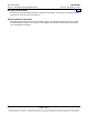
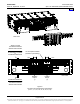
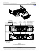
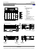
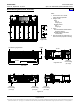
Table Of Contents
- SYSTEM OVERVIEW
- MAIN COMPONENTS ILLUSTRATIONS
- LIST DESCRIPTIONS
- List Numbers
- 588705000 List 1:Rectifier Module Mounting Shelf, 208/240VAC Single-Phase Input, AC Input Terminal Blocks
- 588705000 List 3:Rectifier Module Mounting Shelf, 208/240VAC Three-Phase Input, AC Input Terminal Blocks
- 588705000 List 11:Rectifier Module Mounting Shelf, 208/240VAC Single-Phase Input, AC Input Line Cords
- 588705000 List 21:Rectifier Module Mounting Shelf, 208/240VAC Input, No AC Input Terminal Blocks
- 588705000 List 22:Rectifier Module Mounting Shelf, 208/240VAC Single-Phase Input, AC Input Line Cords
- 588705000 List 31:Rectifier Module Mounting Shelf, 208/240VAC Single-Phase Input, AC Input Terminal Blocks
- 588705000 List 32:Rectifier Module Mounting Shelf, 208/240VAC Three-Phase Input, AC Input Terminal Blocks
- 588705000 List 40:Converter Module Mounting Shelf, 400V DC Input, No DC Input Terminal Blocks
- 588705000 List 41:Converter Module Mounting Shelf, 400V DC Input, DC Input Terminal Blocks
- 588705000 List 42:Converter Module Mounting Shelf, 400V DC Input, DC Input Terminal Blocks
- 588705000 List 51:Expansion Rectifier Module Mounting Shelf, 208/240VAC Single-Phase Input, AC Input Terminal Blocks
- 588705000 List 52:Expansion Rectifier Module Mounting Shelf, 208/240VAC Three-Phase Input, AC Input Terminal Blocks
- 588705000 List 53:Expansion Rectifier Module Mounting Shelf, 208/240VAC Single-Phase Input, AC Input Line Cords
- 588705000 List 61:Main Rectifier Module Mounting Shelf, 208/240VAC Single-Phase Input, AC Input Terminal Blocks
- 588705000 List 62:Main Rectifier Module Mounting Shelf, 208/240VAC Three-Phase Input, AC Input Terminal Blocks
- 588705000 List 63:Main Rectifier Module Mounting Shelf, 208/240VAC Single-Phase Input, AC Input Line Cords
- List Numbers
- ACCESSORY DESCRIPTIONS
- RECOMMENDED WIRE SIZES, BRANCH CIRCUIT PROTECTION, CRIMP LUGS, AND WIRING ILLUSTRATIONS
- Shelf Frame Grounding Connection
- AC Input Connections
- List 1, 31, 51, and 61 Module Mounting Shelf (208/240VAC Single Phase Input)
- List 3, 32, 52, and 62 Module Mounting Shelf (208/240VAC Three Phase Input)
- List 11, 22, 53, and 63 Module Mounting Shelf (208/240VAC Single Phase Input)
- List 41 Module Mounting Shelf (400V DC Input)
- List 42 Module Mounting Shelf (400V DC Input)
- DC Output Connections
- External Alarms Connections
- SPECIFICATIONS
- MECHANICAL SPECIFICATIONS
- RELATED DOCUMENTATION

Power Data Sheet PD588705000
Spec. No. 588705000 (Model PSS4850-23GV) Issue AP, September 12, 2013
Page 35 of 42
This document is property of Emerson Network Power, Energy Systems, North America, Inc. and contains confidential and proprietary information owned by Emerson Network Power, Energy
Systems, North America, Inc. Any copying, use, or disclosure of it without the written permission of Emerson Network Power, Energy Systems, North America, Inc. is strictly prohibited.
• Clearance requirements are:
a) Recommended minimum aisle space clearance for the front of the unit is 2' 6".
b) See Paragraph 3.1.5 for minimum rear spacing requirements.
Note: Minimum rear spacing specified for ventilation may not permit installation and
maintenance of the system.
Recommended minimum aisle space clearance for the rear of each bay is 2’ 0” to
allow for installation and maintenance.
1.4 Compliance Information
1.4.1 Safety Compliance: This unit meets the requirements of UL 60950-1, Standard for Information
Technology Equipment, and is UL Recognized as a power supply for use in Telephone,
Electronic Data Processing or Information Processing Equipment. This unit meets the
requirements of CAN/CSA 22.2, No. 60950-00 and is tested and Certified by UL ("c UR") as a
Component Type Power Supply.
1.5 System Interface Board Ratings (List 61, 62, 63)
1.5.1 Battery Fuse Alarm Input Rating
(A) The default is 400mV. Anything greater than 400mV causes alarm to be raised.
1.5.2 Load Fuse Alarm Input Signal
(A) Anything greater than 19V causes alarm to be raised.
1.5.3 Battery and Load Shunt Input Rating
(A) 1mV – 150mV.
1.5.4 LVD Sense Input Rating
(A) Normal state is at 60V or less. A RTN signal indicates the contactor is open.
1.5.5 LVD Driver Output Rating
(A) Mono-stable, normal state is 60V or less at 1A continuous rating. Normally closed
contactors are used for mono-stable option.
(B) Bi-Stable, normal state less than 60V and 2A at 500ms – 1000ms pulse rating.
1.6 IB2 (ACU+ Interface Board) Ratings (List 61, 62, 63)
1.6.1 Digital Input Ratings
(A) Maximum Voltage Rating: 60V DC.
(B) Active High: > 19V DC.
(C) Active Low: < 1V DC.
1.6.2 Relay Ratings
(A) 1A Steady State @ 30V DC.
(B) 3A Peak @ 30V DC.
2. RECTIFIER SPECIFICATIONS
Refer to the separate Rectifier Instruction Document (UM1R483500E).
3. CONVERTER SPECIFICATIONS
Refer to the separate Converter Instruction Document (UM1C400483500E).
Home