
Brochures and Data Sheets
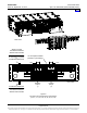
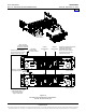
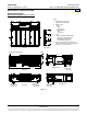
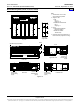
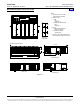
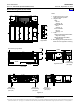
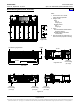
Table Of Contents
- SYSTEM OVERVIEW
- MAIN COMPONENTS ILLUSTRATIONS
- LIST DESCRIPTIONS
- List Numbers
- 588705000 List 1:Rectifier Module Mounting Shelf, 208/240VAC Single-Phase Input, AC Input Terminal Blocks
- 588705000 List 3:Rectifier Module Mounting Shelf, 208/240VAC Three-Phase Input, AC Input Terminal Blocks
- 588705000 List 11:Rectifier Module Mounting Shelf, 208/240VAC Single-Phase Input, AC Input Line Cords
- 588705000 List 21:Rectifier Module Mounting Shelf, 208/240VAC Input, No AC Input Terminal Blocks
- 588705000 List 22:Rectifier Module Mounting Shelf, 208/240VAC Single-Phase Input, AC Input Line Cords
- 588705000 List 31:Rectifier Module Mounting Shelf, 208/240VAC Single-Phase Input, AC Input Terminal Blocks
- 588705000 List 32:Rectifier Module Mounting Shelf, 208/240VAC Three-Phase Input, AC Input Terminal Blocks
- 588705000 List 40:Converter Module Mounting Shelf, 400V DC Input, No DC Input Terminal Blocks
- 588705000 List 41:Converter Module Mounting Shelf, 400V DC Input, DC Input Terminal Blocks
- 588705000 List 42:Converter Module Mounting Shelf, 400V DC Input, DC Input Terminal Blocks
- 588705000 List 51:Expansion Rectifier Module Mounting Shelf, 208/240VAC Single-Phase Input, AC Input Terminal Blocks
- 588705000 List 52:Expansion Rectifier Module Mounting Shelf, 208/240VAC Three-Phase Input, AC Input Terminal Blocks
- 588705000 List 53:Expansion Rectifier Module Mounting Shelf, 208/240VAC Single-Phase Input, AC Input Line Cords
- 588705000 List 61:Main Rectifier Module Mounting Shelf, 208/240VAC Single-Phase Input, AC Input Terminal Blocks
- 588705000 List 62:Main Rectifier Module Mounting Shelf, 208/240VAC Three-Phase Input, AC Input Terminal Blocks
- 588705000 List 63:Main Rectifier Module Mounting Shelf, 208/240VAC Single-Phase Input, AC Input Line Cords
- List Numbers
- ACCESSORY DESCRIPTIONS
- RECOMMENDED WIRE SIZES, BRANCH CIRCUIT PROTECTION, CRIMP LUGS, AND WIRING ILLUSTRATIONS
- Shelf Frame Grounding Connection
- AC Input Connections
- List 1, 31, 51, and 61 Module Mounting Shelf (208/240VAC Single Phase Input)
- List 3, 32, 52, and 62 Module Mounting Shelf (208/240VAC Three Phase Input)
- List 11, 22, 53, and 63 Module Mounting Shelf (208/240VAC Single Phase Input)
- List 41 Module Mounting Shelf (400V DC Input)
- List 42 Module Mounting Shelf (400V DC Input)
- DC Output Connections
- External Alarms Connections
- SPECIFICATIONS
- MECHANICAL SPECIFICATIONS
- RELATED DOCUMENTATION

PD588705000 Power Data Sheet
Issue AP, September 12, 2013 Spec. No. 588705000 (Model PSS4850-23GV)
Page 34 of 42
This document is property of Emerson Network Power, Energy Systems, North America, Inc. and contains confidential and proprietary information owned by Emerson Network Power, Energy
Systems, North America, Inc. Any copying, use, or disclosure of it without the written permission of Emerson Network Power, Energy Systems, North America, Inc. is strictly prohibited.
SPECIFICATIONS
Note: Refer to the separate System Application Guide (SAG) of the associated Power System for the following:
• MCA Controller specifications and factory default settings.
• ACU+ Controller specifications and factory default settings.
• All external alarms.
• All external controls.
• Local status and alarm indicators other than those provided on the rectifier and converter modules.
1. MODULE MOUNTING SHELF SPECIFICATIONS
1.1 Output Ratings
1.1.1 See page 2.
1.2 Input Ratings
1.2.1 See page 2.
1.3 Environmental Ratings
1.3.1 Operating Ambient Temperature Range: -40°C to +65°C (-40°F to +149°F).
1.3.2 Storage Ambient Temperature Range: -40°C to +85°C (-40°F to +185°F).
1.3.3 Humidity: Capable of operating in an ambient relative humidity range of 0% to 95%, non-
condensing.
1.3.4 Altitude: Capable of operating in an altitude range of -200 feet to 10,000 feet. The maximum
operating ambient temperature should be de-rated by 3°C per 1000 feet above 5000 feet.
1.3.5 Ventilation Requirements:
(A) Ventilation: A module mounting shelf must be mounted so ventilating openings are not
blocked and temperature of the air entering the cabinet does not exceed the Operating
Ambient Temperature Range stated above. The distance from the rear of a module
mounting shelf to a wall or other solid structure must not be less than two (2) inches. This
will assure proper airflow through the rectifier modules. (See also Paragraph 3.1.6.)
(B) Stacking Considerations: This system is designed for front to back ventilation to facilitate
stacking of module mounting shelves, one above the other, in a relay rack. There is no
spacing requirement between stacked module mounting shelves of a single system.
1.3.6 Mounting: The module mounting shelves are designed for mounting in a 23 inch wide relay
rack with 1 inch or 1-3/4 inch multiple drilling. For Lists 1, 3, and 11; mounting angles can be
positioned from flush-front mounting to 6-inch front projection mounting, in 1-inch increments.
For Lists 21, 22, 31, 32, 40, 41, and 42; mounting angles are positioned for a fixed 9-inch front
projection mounting. For Lists 51, 52, 53, 61, 62, and 63; mounting angles are positioned for a
fixed 6-inch front projection mounting. Refer to Overall Dimensions starting on page 36 for
dimensional illustrations.
• This product is intended only for installation in a restricted access location on or above a
non-combustible surface.
• This product must be located in a controlled environment with access to crafts persons only.
• This product is intended for installation in network telecommunication facilities (CO, vault,
hut, or other environmentally controlled electronic equipment enclosure).
• This product is intended to be connected to the common bonding network in a network
telecommunication facility (CO, vault, hut, or other environmentally controlled electronic
equipment enclosure).
• The DC return connection to this system can remain isolated from system frame and chassis
(DC-I).
• This system is suitable for installation as part of the Common Bonding Network (CBN).
• Rectifier and module mounting shelf ventilating openings must not be blocked and
temperature of air entering rectifiers must not exceed the rated operating ambient
temperature range.
Home