
Brochures and Data Sheets
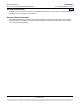
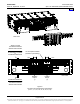
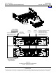
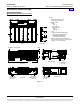
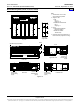
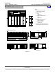
Table Of Contents
- SYSTEM OVERVIEW
- MAIN COMPONENTS ILLUSTRATIONS
- LIST DESCRIPTIONS
- List Numbers
- 588705000 List 1:Rectifier Module Mounting Shelf, 208/240VAC Single-Phase Input, AC Input Terminal Blocks
- 588705000 List 3:Rectifier Module Mounting Shelf, 208/240VAC Three-Phase Input, AC Input Terminal Blocks
- 588705000 List 11:Rectifier Module Mounting Shelf, 208/240VAC Single-Phase Input, AC Input Line Cords
- 588705000 List 21:Rectifier Module Mounting Shelf, 208/240VAC Input, No AC Input Terminal Blocks
- 588705000 List 22:Rectifier Module Mounting Shelf, 208/240VAC Single-Phase Input, AC Input Line Cords
- 588705000 List 31:Rectifier Module Mounting Shelf, 208/240VAC Single-Phase Input, AC Input Terminal Blocks
- 588705000 List 32:Rectifier Module Mounting Shelf, 208/240VAC Three-Phase Input, AC Input Terminal Blocks
- 588705000 List 40:Converter Module Mounting Shelf, 400V DC Input, No DC Input Terminal Blocks
- 588705000 List 41:Converter Module Mounting Shelf, 400V DC Input, DC Input Terminal Blocks
- 588705000 List 42:Converter Module Mounting Shelf, 400V DC Input, DC Input Terminal Blocks
- 588705000 List 51:Expansion Rectifier Module Mounting Shelf, 208/240VAC Single-Phase Input, AC Input Terminal Blocks
- 588705000 List 52:Expansion Rectifier Module Mounting Shelf, 208/240VAC Three-Phase Input, AC Input Terminal Blocks
- 588705000 List 53:Expansion Rectifier Module Mounting Shelf, 208/240VAC Single-Phase Input, AC Input Line Cords
- 588705000 List 61:Main Rectifier Module Mounting Shelf, 208/240VAC Single-Phase Input, AC Input Terminal Blocks
- 588705000 List 62:Main Rectifier Module Mounting Shelf, 208/240VAC Three-Phase Input, AC Input Terminal Blocks
- 588705000 List 63:Main Rectifier Module Mounting Shelf, 208/240VAC Single-Phase Input, AC Input Line Cords
- List Numbers
- ACCESSORY DESCRIPTIONS
- RECOMMENDED WIRE SIZES, BRANCH CIRCUIT PROTECTION, CRIMP LUGS, AND WIRING ILLUSTRATIONS
- Shelf Frame Grounding Connection
- AC Input Connections
- List 1, 31, 51, and 61 Module Mounting Shelf (208/240VAC Single Phase Input)
- List 3, 32, 52, and 62 Module Mounting Shelf (208/240VAC Three Phase Input)
- List 11, 22, 53, and 63 Module Mounting Shelf (208/240VAC Single Phase Input)
- List 41 Module Mounting Shelf (400V DC Input)
- List 42 Module Mounting Shelf (400V DC Input)
- DC Output Connections
- External Alarms Connections
- SPECIFICATIONS
- MECHANICAL SPECIFICATIONS
- RELATED DOCUMENTATION
Power Data Sheet PD588705000
Spec. No. 588705000 (Model PSS4850-23GV) Issue AP, September 12, 2013
Page 33 of 42
This document is property of Emerson Network Power, Energy Systems, North America, Inc. and contains confidential and proprietary information owned by Emerson Network Power, Energy
Systems, North America, Inc. Any copying, use, or disclosure of it without the written permission of Emerson Network Power, Energy Systems, North America, Inc. is strictly prohibited.
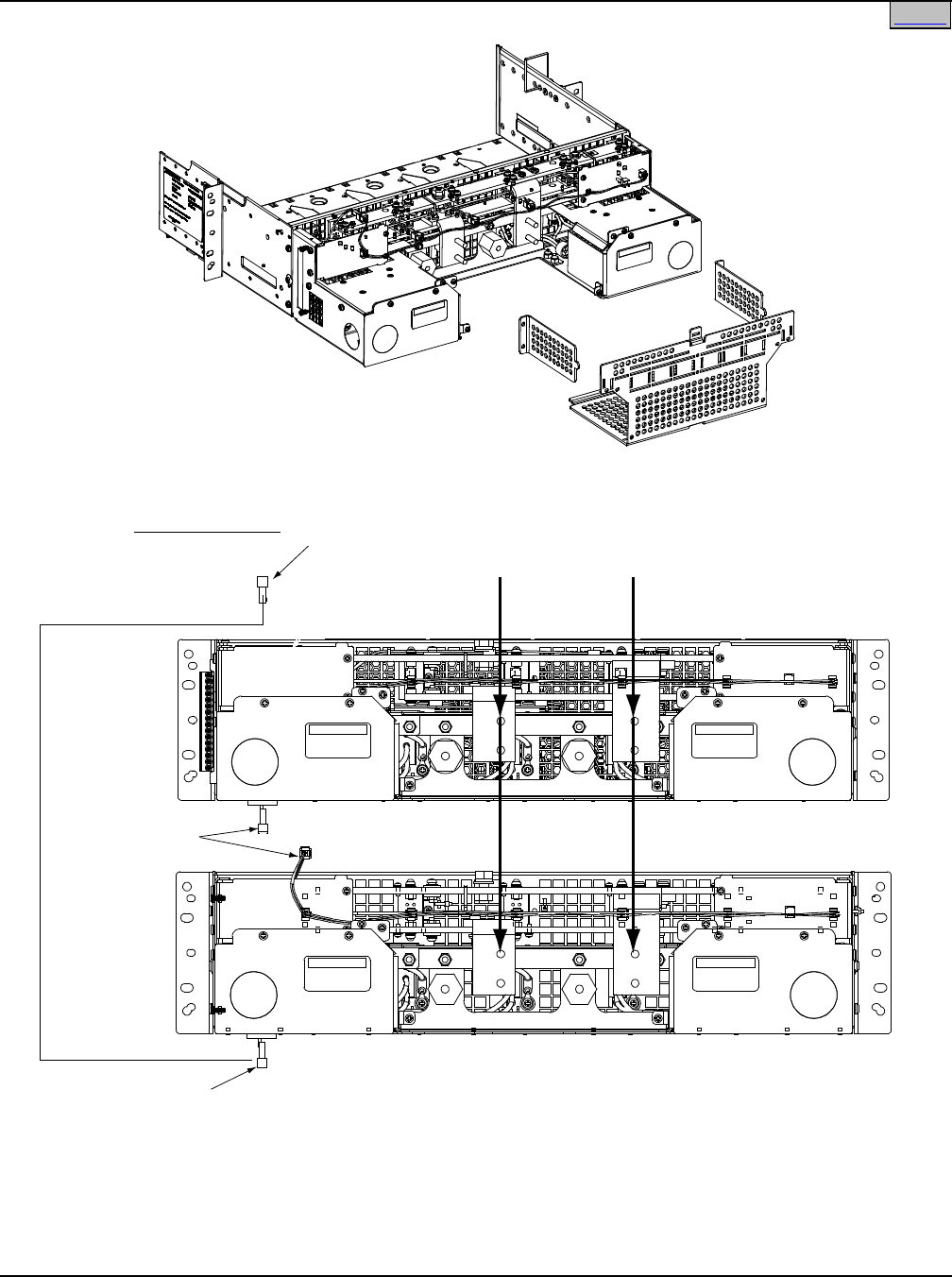
Figure 10
DC Output and Alarm/Control Connections
(List 51, 52, 53, 61, 62, 63)
Ne
gative
Output Busbar
(-)
Positive
Output Busbar
(+)
termination
plug located
in this connector
System using these shelves
may provide a jumper to bring
bottom connector up to top.
To connector in
shelf mounted below or
if last shelf termination
plug is located here.
Alarm & Control
Connections Between
Shelves and Controller
These two connectors
are plugged together.
Rear View (Main Shelf)
(List 61 shown)
Rear View (Expansion Shelf)
(List 51 shown)
Rear View
(List 51 shown)
Shelf(s) DC output lug termination
busbars provided with the
associated power system.
Refer to the power system’s
documention for busbar lug
hole size and spacing.
Home