
Brochures and Data Sheets
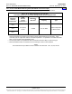
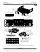
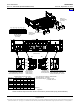
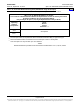
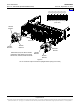
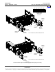
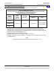
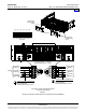
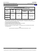
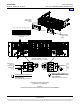
Table Of Contents
- SYSTEM OVERVIEW
- MAIN COMPONENTS ILLUSTRATIONS
- LIST DESCRIPTIONS
- List Numbers
- 588705000 List 1:Rectifier Module Mounting Shelf, 208/240VAC Single-Phase Input, AC Input Terminal Blocks
- 588705000 List 3:Rectifier Module Mounting Shelf, 208/240VAC Three-Phase Input, AC Input Terminal Blocks
- 588705000 List 11:Rectifier Module Mounting Shelf, 208/240VAC Single-Phase Input, AC Input Line Cords
- 588705000 List 21:Rectifier Module Mounting Shelf, 208/240VAC Input, No AC Input Terminal Blocks
- 588705000 List 22:Rectifier Module Mounting Shelf, 208/240VAC Single-Phase Input, AC Input Line Cords
- 588705000 List 31:Rectifier Module Mounting Shelf, 208/240VAC Single-Phase Input, AC Input Terminal Blocks
- 588705000 List 32:Rectifier Module Mounting Shelf, 208/240VAC Three-Phase Input, AC Input Terminal Blocks
- 588705000 List 40:Converter Module Mounting Shelf, 400V DC Input, No DC Input Terminal Blocks
- 588705000 List 41:Converter Module Mounting Shelf, 400V DC Input, DC Input Terminal Blocks
- 588705000 List 42:Converter Module Mounting Shelf, 400V DC Input, DC Input Terminal Blocks
- 588705000 List 51:Expansion Rectifier Module Mounting Shelf, 208/240VAC Single-Phase Input, AC Input Terminal Blocks
- 588705000 List 52:Expansion Rectifier Module Mounting Shelf, 208/240VAC Three-Phase Input, AC Input Terminal Blocks
- 588705000 List 53:Expansion Rectifier Module Mounting Shelf, 208/240VAC Single-Phase Input, AC Input Line Cords
- 588705000 List 61:Main Rectifier Module Mounting Shelf, 208/240VAC Single-Phase Input, AC Input Terminal Blocks
- 588705000 List 62:Main Rectifier Module Mounting Shelf, 208/240VAC Three-Phase Input, AC Input Terminal Blocks
- 588705000 List 63:Main Rectifier Module Mounting Shelf, 208/240VAC Single-Phase Input, AC Input Line Cords
- List Numbers
- ACCESSORY DESCRIPTIONS
- RECOMMENDED WIRE SIZES, BRANCH CIRCUIT PROTECTION, CRIMP LUGS, AND WIRING ILLUSTRATIONS
- Shelf Frame Grounding Connection
- AC Input Connections
- List 1, 31, 51, and 61 Module Mounting Shelf (208/240VAC Single Phase Input)
- List 3, 32, 52, and 62 Module Mounting Shelf (208/240VAC Three Phase Input)
- List 11, 22, 53, and 63 Module Mounting Shelf (208/240VAC Single Phase Input)
- List 41 Module Mounting Shelf (400V DC Input)
- List 42 Module Mounting Shelf (400V DC Input)
- DC Output Connections
- External Alarms Connections
- SPECIFICATIONS
- MECHANICAL SPECIFICATIONS
- RELATED DOCUMENTATION
Power Data Sheet PD588705000
Spec. No. 588705000 (Model PSS4850-23GV) Issue AP, September 12, 2013
Page 29 of 42
This document is property of Emerson Network Power, Energy Systems, North America, Inc. and contains confidential and proprietary information owned by Emerson Network Power, Energy
Systems, North America, Inc. Any copying, use, or disclosure of it without the written permission of Emerson Network Power, Energy Systems, North America, Inc. is strictly prohibited.
List 42 Module Mounting Shelf (400V DC Input)
Refer to Table 6 for recommended wire size and Figure 8 for terminal location.
LIST 42 DC INPUT (TB1 and TB2)
Connection Points for Two DC Input Feeds are Provided per Shelf
Operating
Ambient
Temperature
1
Recm
Branch
Circuit
Protection
3, 4
Recm 90
°
C
Wire Size
1, 5
TB1 and TB2 Terminals
Capacity Type
45°C
45 Amperes 6 AWG 6 to 14 AWG
Screw Compression
Tubular Contact
50°C
65°C
2
1
Wire sizes based on recommendations of the American National Standards Institute (ANSI)
approved National Fire Protection Association's (NFPA) National Electrical Code (NEC). Table
310.15 (B) (16) for copper wire at 90°C conductor temperature. For operation in countries where the
NEC is not recognized, follow applicable codes.
2
Converters de-rate to 2700W at an ambient of 65°C.
3
Recommendations based on Full Load Input Current of 33 Amperes.
4
Maximum overcurrent protective device is 60A at 40°C.
5
Maximum loop length is 100 meters (328 feet). Loop length is the sum of the lengths of the positive
and negative leads.
Table 6
Recommended DC Input Branch Circuit Protection and Wire Size - List 42
Home