
Brochures and Data Sheets
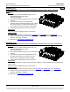
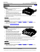
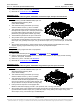
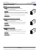
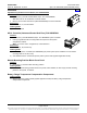
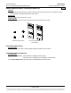
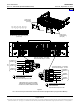
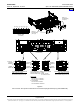
Table Of Contents
- SYSTEM OVERVIEW
- MAIN COMPONENTS ILLUSTRATIONS
- LIST DESCRIPTIONS
- List Numbers
- 588705000 List 1:Rectifier Module Mounting Shelf, 208/240VAC Single-Phase Input, AC Input Terminal Blocks
- 588705000 List 3:Rectifier Module Mounting Shelf, 208/240VAC Three-Phase Input, AC Input Terminal Blocks
- 588705000 List 11:Rectifier Module Mounting Shelf, 208/240VAC Single-Phase Input, AC Input Line Cords
- 588705000 List 21:Rectifier Module Mounting Shelf, 208/240VAC Input, No AC Input Terminal Blocks
- 588705000 List 22:Rectifier Module Mounting Shelf, 208/240VAC Single-Phase Input, AC Input Line Cords
- 588705000 List 31:Rectifier Module Mounting Shelf, 208/240VAC Single-Phase Input, AC Input Terminal Blocks
- 588705000 List 32:Rectifier Module Mounting Shelf, 208/240VAC Three-Phase Input, AC Input Terminal Blocks
- 588705000 List 40:Converter Module Mounting Shelf, 400V DC Input, No DC Input Terminal Blocks
- 588705000 List 41:Converter Module Mounting Shelf, 400V DC Input, DC Input Terminal Blocks
- 588705000 List 42:Converter Module Mounting Shelf, 400V DC Input, DC Input Terminal Blocks
- 588705000 List 51:Expansion Rectifier Module Mounting Shelf, 208/240VAC Single-Phase Input, AC Input Terminal Blocks
- 588705000 List 52:Expansion Rectifier Module Mounting Shelf, 208/240VAC Three-Phase Input, AC Input Terminal Blocks
- 588705000 List 53:Expansion Rectifier Module Mounting Shelf, 208/240VAC Single-Phase Input, AC Input Line Cords
- 588705000 List 61:Main Rectifier Module Mounting Shelf, 208/240VAC Single-Phase Input, AC Input Terminal Blocks
- 588705000 List 62:Main Rectifier Module Mounting Shelf, 208/240VAC Three-Phase Input, AC Input Terminal Blocks
- 588705000 List 63:Main Rectifier Module Mounting Shelf, 208/240VAC Single-Phase Input, AC Input Line Cords
- List Numbers
- ACCESSORY DESCRIPTIONS
- RECOMMENDED WIRE SIZES, BRANCH CIRCUIT PROTECTION, CRIMP LUGS, AND WIRING ILLUSTRATIONS
- Shelf Frame Grounding Connection
- AC Input Connections
- List 1, 31, 51, and 61 Module Mounting Shelf (208/240VAC Single Phase Input)
- List 3, 32, 52, and 62 Module Mounting Shelf (208/240VAC Three Phase Input)
- List 11, 22, 53, and 63 Module Mounting Shelf (208/240VAC Single Phase Input)
- List 41 Module Mounting Shelf (400V DC Input)
- List 42 Module Mounting Shelf (400V DC Input)
- DC Output Connections
- External Alarms Connections
- SPECIFICATIONS
- MECHANICAL SPECIFICATIONS
- RELATED DOCUMENTATION
PD588705000 Power Data Sheet
Issue AP, September 12, 2013 Spec. No. 588705000 (Model PSS4850-23GV)
Page 16 of 42
This document is property of Emerson Network Power, Energy Systems, North America, Inc. and contains confidential and proprietary information owned by Emerson Network Power, Energy
Systems, North America, Inc. Any copying, use, or disclosure of it without the written permission of Emerson Network Power, Energy Systems, North America, Inc. is strictly prohibited.
Converters
High Efficiency DC-DC Converter Module, P/N 1C400483500E
Features
♦ Provides one (1) Model C400/48-3500e, Spec. No. 1C400483500E,
3500 watt / 400 to -48 volt DC-DC converter module.
♦ Refer to the Converter Instructions (UM1C400483500E) for more information.
Restrictions
For use in List 40, 41, and 42 shelves.
Ordering Notes
1) Order as required.
ACU+ Controller (Advanced Control Unit Plus), P/N 1M820DNA
Features
♦ Provides one (1) Model M820DNA, Spec. No. 1M820DNA system controller.
♦ Factory programmed with the configuration file required for the system
configuration ordered.
Note: For custom ACU+ configurations, contact Emerson.
Restrictions
For use in List 61, 62, and 63 only.
Ordering Notes
1) Order one (1) ACU+ Controller (P/N 1M820DNA) per power system (to be installed in a main module
mounting shelf List 61, 62, or 63).
2) Oder additional ACU+ accessories per the power system’s SAG (System Application Guide).
Module Mounting Position Blank Cover Panel
Features
♦ Covers one (1) unused module mounting position.
Ordering Notes
1) Order a module mounting position blank cover panel, P/N 21140440, for each empty module mounting
position in the system, as desired.
Battery Charge Temperature Compensation Components
Ordering Notes
1) Refer to the power system’s SAG (System Application Guide) for battery charge temperature
compensation components.
Home