
Brochures and Data Sheets


UM1R483500E User Instructions
Issue AG, November 20, 2012 Spec. No. 1R483200 (Model R48-3200)
Spec. No. 1R483200E (Model R48-3200E)
Spec. No. 1R483500E (Model R48-3500E)
Page 22
This document is property of Emerson Network Power, Energy Systems, North America, Inc. and contains confidential and proprietary information owned by Emerson Network Power, Energy
Systems, North America, Inc. Any copying, use, or disclosure of it without the written permission of Emerson Network Power, Energy Systems, North America, Inc. is strictly prohibited.
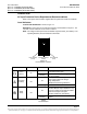
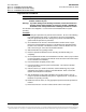
Rectifier Fan Replacement
Each Rectifier uses a fan (P/N 32010086 for 1R483200 rectifier module. P/N 32010109
for 1R483200E and 1R483500E rectifier module) for cooling. If fan replacement should
become necessary, perform the following procedure.
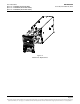
Refer to Figure 14 as this procedure is performed.
Caution: In a system with NO redundant Rectifier, battery must have sufficient
reserve to power the load(s) while the Rectifier is removed for fan
replacement.
Note: When performing any step in this procedure that requires removal of existing
hardware, retain all hardware for use in subsequent steps.
Procedure
1) Performing this procedure may activate external alarms. Do one of the following.
If possible, disable these alarms. If these alarms cannot be easily disabled,
notify the appropriate personnel to disregard any alarms associated with this
system while this procedure is performed.
2) Remove the Rectifier from the shelf. Refer to a previous procedure for step-by-
step instructions.
3) Place the Rectifier Module on a static-safe work surface. Connect an approved
grounding strap to your wrist for the remainder of this procedure.
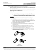
4) On this Rectifier, loosen the three (3) screws on the Rectifier front cover and
remove the cover.
5) For proper orientation of the new fan, observe the location of the fan wires and
the air flow arrows on the old fan.
6) Unplug the power cable of the old fan and remove the fan.
7) Plug the power cable of the new fan and place the new fan in the space vacated
by the old fan. Ensure the fan wires and air flow arrows match the orientation of
the old fan.
8) Position the Rectifier front cover back into place and secure with the screws
previously removed.
9) Replace the Rectifier into the shelf. Refer to the previous procedure for step-by-
step instructions.
10) When the fans start, check to ensure that each is providing front-to-back airflow.
If air direction is wrong, immediately remove the Rectifier Module from the shelf.
Repeat previous steps to check fan orientation, and correct as necessary.
Reinstall the Rectifier Module and again check for proper airflow.
11) Enable the external alarms, or notify appropriate personnel that this procedure is
finished.
12) Ensure that there are no local or remote alarms active on the system.