
Brochures and Data Sheets


User Instructions UM1R483500E
Spec. No. 1R483200 (Model R48-3200) Issue AG, November 20, 2012
Spec. No. 1R483200E (Model R48-3200E)
Spec. No. 1R483500E (Model R48-3500E)
Page 21
This document is property of Emerson Network Power, Energy Systems, North America, Inc. and contains confidential and proprietary information owned by Emerson Network Power, Energy
Systems, North America, Inc. Any copying, use, or disclosure of it without the written permission of Emerson Network Power, Energy Systems, North America, Inc. is strictly prohibited.
Replacement Procedures
Rectifier Replacement
Danger: Take care when removing a Rectifier that was in operation, as Rectifier
surfaces could be very hot.
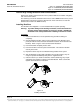
Warning: To prevent damage to the latching mechanism, ensure the handle is in
the open position when installing or removing a module. NEVER hold
the handle in the closed position when installing a module into a shelf.
The Rectifier is hot swappable. It can be removed and installed with the system
operating.
Procedure
1) Performing this procedure may activate external alarms. Do one of the following.
If possible, disable these alarms. If these alarms cannot be easily disabled,
notify the appropriate personnel to disregard any alarms associated with this
system while this procedure is performed.
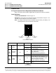
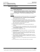
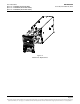
2) On the Rectifier to be removed, click the Rectifier’s handle in order to pop it
forward out of the Rectifier's front panel. This will retract the latch mechanism
located on the underside of the Rectifier and thus unlock the Rectifier from the
shelf. Refer to Figure 13 for latch mechanism illustration.
3) Slide the Rectifier out by pulling forward.
4) Place the replacement Rectifier into the mounting slot without sliding it in
completely.
5) On the replacement Rectifier, click the Rectifier’s handle in order to pop it forward
out of the Rectifier's front panel (this will also retract the latch mechanism located
on the underside of the Rectifier).
6) Push the Rectifier completely into the shelf.
7) Push the handle into the front panel of the Rectifier. This locks the Rectifier
securely to the shelf.
8) Certain functions (i.e. rectifier current limit, rectifier addressing) may require
adjustment when adding or replacing a Rectifier Module. Refer to the Power
System documentation for instructions.
9) After the Rectifiers are physically installed in the mounting shelf(s), they are
ready for operation immediately after power is supplied to them. Verify that the
Rectifiers are operating normally.
10) Enable the external alarms, or notify appropriate personnel that this procedure is
finished.
11) Ensure that there are no local or remote alarms active on the system.