
Brochures and Data Sheets


UM1R483500E User Instructions
Issue AG, November 20, 2012 Spec. No. 1R483200 (Model R48-3200)
Spec. No. 1R483200E (Model R48-3200E)
Spec. No. 1R483500E (Model R48-3500E)
Page 20
This document is property of Emerson Network Power, Energy Systems, North America, Inc. and contains confidential and proprietary information owned by Emerson Network Power, Energy
Systems, North America, Inc. Any copying, use, or disclosure of it without the written permission of Emerson Network Power, Energy Systems, North America, Inc. is strictly prohibited.
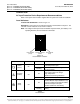
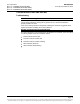
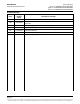
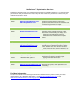
Symptom
Possible Cause(s)
Suggested Action(s)
Power
Indicator
(Green) Off
No input voltage.
Make sure there is input voltage.
Internal input fuse open.
Replace the Rectifier.
Protection
Indicator
(Yellow) On
AC input voltage outside the
normal range.
Correct the AC input voltage to
within the acceptable range.
PFC over-voltage.
Replace the Rectifier.
Moderate load sharing imbalance.
Replace the Rectifier.
Rectifier not inserted into the slot
completely.
Remove and properly insert the
Rectifier.
Rectifier over-temperature protection, which could be caused by:
1. Fan rotor blocked.
1. Remove any object that may
be blocking the fan.
2. Ventilation blocked (inlet or
outlet).
2. Remove any object that may
be blocking the inlet or outlet.
3. Ambient temperature too high
or Rectifier inlet too close to a
heat source.
3. Lower the ambient temperature
or relocate the heat source.
Protection
Indicator
(Yellow)
Flashing
Rectifier communication failure.
Check the communication cables.
Remove and properly insert the
Rectifier.
Alarm
Indicator
(Red) On
Output over-voltage shutdown.
Severe load sharing imbalance.
Internal output fuse open.
Remove the Rectifier, wait 30
seconds or more (until the LEDs
on the rectifier extinguish), then
re-insert the Rectifier. If Rectifier
fails to start or shuts down again;
replace the Rectifier.
Alarm
Indicator
(Red)
Flashing
Fan not operating
(Rectifier shuts down).
Replace the fan.
Table 3
Rectifier Troubleshooting