
Brochures and Data Sheets

UM1R483500E User Instructions
Issue AG, November 20, 2012 Spec. No. 1R483200 (Model R48-3200)
Spec. No. 1R483200E (Model R48-3200E)
Spec. No. 1R483500E (Model R48-3500E)
Page 18
This document is property of Emerson Network Power, Energy Systems, North America, Inc. and contains confidential and proprietary information owned by Emerson Network Power, Energy
Systems, North America, Inc. Any copying, use, or disclosure of it without the written permission of Emerson Network Power, Energy Systems, North America, Inc. is strictly prohibited.
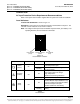
Rectifier High Voltage Shutdown and Lockout Restart
Remove the rectifier, wait 30 seconds or more (until the LEDs on the rectifier extinguish),
then re-insert the rectifier.
The rectifier(s) can also be restarted from the ACU+ LCD or WEB Interface menu (via the
Rectifier Reset command, found in the Manual menu in the LCD menus or under the
Rectifier Control Tab in the WEB Interface).
Installing Rectifiers
The Rectifier is hot swappable. It can be installed with the system operating.
Warning: To prevent damage to the latching mechanism, ensure the handle is in
the open position when installing or removing a module. NEVER hold
the handle in the closed position when installing a module into a shelf.
Procedure
1) Place the Rectifier into an unoccupied mounting slot without sliding it in
completely.
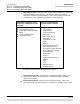
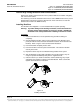
2) Click the Rectifier handle in order to pop it forward out of the Rectifier's front
panel (this will also retract the latch mechanism located on the underside of the
Rectifier). Refer to Figure 13 for latch mechanism illustration.
3) Push the Rectifier completely into the shelf.
4) Push the handle into the front panel of the Rectifier. This locks the Rectifier
securely to the shelf.
5) Repeat the above steps for each Rectifier being installed in the system.
6) After the Rectifiers are physically installed in the mounting shelf(s), they are
ready for operation immediately after power is supplied to them.
7) Certain functions (i.e. rectifier current limit, rectifier addressing) may require
adjustment when adding or replacing a Rectifier Module. Refer to the Power
System documentation for instructions.
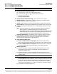
Figure 13
Installing a Rectifier