
Brochures and Data Sheets

User Instructions UM1R483500E
Spec. No. 1R483200 (Model R48-3200) Issue AG, November 20, 2012
Spec. No. 1R483200E (Model R48-3200E)
Spec. No. 1R483500E (Model R48-3500E)
Page 17
This document is property of Emerson Network Power, Energy Systems, North America, Inc. and contains confidential and proprietary information owned by Emerson Network Power, Energy
Systems, North America, Inc. Any copying, use, or disclosure of it without the written permission of Emerson Network Power, Energy Systems, North America, Inc. is strictly prohibited.
OPERATION
AC Input Protection Device Requirements/Recommendations
Refer to the system documentation supplied with the system the rectifier is installed in.
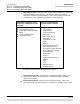
Local Indicators
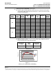
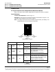
Location and Identification: Refer to Figure 12.
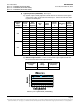
Description: There are three (3) indicators located on the Rectifier’s front panel. The
functions of these indicators are as shown in Table 2.
Note: DC voltage must be present at the Rectifier output terminals, (from battery or an
operating Rectifier) for local indicators to illuminate.
Figure 12
Local Indicator Locations
Indicator
Normal State
Alarm State
Alarm Cause
Power
(Green)
On
Off
No input voltage.
Internal input fuse open.
Flashing
The Rectifier Module is being identified
by the Controller.
Protection
(Yellow)
Off
On
AC input under/over voltage.
PFC output under/over voltage.
High temperature.
Moderate load sharing imbalance.
Flashing
Loss of communication with controller.
Alarm
(Red)
Off
On
Severe load sharing imbalance.
Rectifier Module output disabled for any
reason, including overvoltage shutdown
and internal output fuse open.
Rectifier addresses contradictory.
Flashing
Faulty fan (Rectifier Module shuts
down).
Table 2
Local Indicators
Power Indicator
(Green)
Protection Indicator
(Yellow)
Alarm Indicator
(Red)