
Brochures and Data Sheets

User Instructions UM1R483500E
Spec. No. 1R483200 (Model R48-3200) Issue AG, November 20, 2012
Spec. No. 1R483200E (Model R48-3200E)
Spec. No. 1R483500E (Model R48-3500E)
Page 13
This document is property of Emerson Network Power, Energy Systems, North America, Inc. and contains confidential and proprietary information owned by Emerson Network Power, Energy
Systems, North America, Inc. Any copying, use, or disclosure of it without the written permission of Emerson Network Power, Energy Systems, North America, Inc. is strictly prohibited.
If two or more Rectifier are installed in a shelf, or if the shelf is paralleled with
other Rectifier Mounting Shelves, only the Rectifier causing the high voltage
condition shuts down.
2) Backup: If Rectifier output voltage exceeds a second (non-adjustable)
value, the Rectifier shuts down and locks out regardless of load. Manual
restart is then required.
Over-Temperature Protection: The Rectifier provides overtemperature protection
by derating output power and recovers automatically.
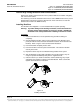
Hot Swappable: The Rectifier is designed to be plug-and-play. The Rectifier can be
inserted or removed from a live DC power system with no damage. When the
Rectifier is plugged into the system, the system output voltage will not be affected.
High Temperature Alarm: Each Rectifier continuously monitors the ambient
temperature surrounding the power conversion circuit. If this temperature exceeds a
preset non-adjustable value, local and extended Rectifier Fail alarms are activated.
The alarms will automatically be removed when the ambient temperature surrounding
the power conversion circuit decreases to below a preset non-adjustable value.
Cooling: Each Rectifier Module contains a fan for front-to-back force air-cooling.
a) Fan Fault Protection: The Rectifier Module shuts down and its alarm indicator
(red) flashes if the fan fails. Fan failure is detected and reported to Controller.
The fans are field replaceable.
b) Fan Control: Fan speed is continuously variable. When input voltage is within
normal range, the built-in processor adjusts fan speed according to the Rectifier
Module’s internal temperature and output power. For example, a higher
temperature or output power increases the fan speed. This feature can be
disabled via the controller, allowing the fan to run at full speed regardless of
temperature.
Paralleling: This Rectifier may be connected in parallel with any Rectifier of the
same polarity and adjusted to the same output voltage.
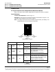
Output Current Walk-In:
a) Normal Start:
Start up time, defined as beginning at AC switch on and ending when full
output power has been reached, consists of two time intervals, the delay
period and the output voltage rampup period.
During the delay period the output voltage will be zero.
Start up time (AC on, till full power): ≤ 5 seconds.
Output voltage ramp up period, t: 50 ≤ t ≤ 150 ms.
(10% to 90% of full power)
The Rectifier will not suffer any damage, when subjected to repetitive AC
switch on / switch off operations.
b) Current Walk-In (if enabled via Controller):
90% load in > 8S, 100% load in < 124s.
According to Telcordia GR-947-CORE, R3-19.