
Brochures and Data Sheets
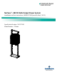

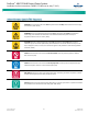

Table Of Contents
- Admonishments Used In This Document
- Important Safety Instructions
- Static Warning
- System Overview
- Installation Acceptance Checklist
- Installing the System
- General Requirements
- Securing the Relay Rack to the Floor
- Mounting System Components in a Relay Rack
- Setting Switch Options
- Making Electrical Connections
- Important Safety Instructions
- Wiring Considerations
- Relay Rack Grounding Connection (Frame Ground)
- AC Input and AC Input Equipment Grounding Connections to Rectifier Module Mounting Shelves
- External Alarm, Reference, Monitoring, and Control Connections
- ACU+ Controller Ethernet Connection (if required)
- -48V DC Output Connections
- Installing the Rectifier Modules and Initially Starting the System
- Installing the Rectifier Modules into Spec. No. 588705000 Rectifier Module Mounting Shelves
- Initially Starting, Configuring, and Checking System Operation
- Important Safety Instructions
- Initial Startup Preparation
- Initially Starting the System
- ACU+ Controller Initialization
- Verifying the Configuration File
- Checking Basic System Settings
- Changing Battery Capacity Rating in the ACU+
- Configuring the ACU+ Identification of Rectifiers and Assigning which Input Phase is Connected to the Rectifiers
- ACU+ Alarm Relay Check
- Checking System Status
- Final Steps
- Operating Procedures
- Maintenance
- Troubleshooting and Repair
- NetPerform™ Optimization Services
NetSure
™
-48V DC Bulk Output Power System
Installation and User Instructions, UM582127100 (Issue AA, May 7, 2013)
Spec. No: 582127100 UM582127100
Model No: 722NBBB Issue AA, May 7, 2013
1
System Overview
Customer Documentation Package
This document (UM582127100) provides Installation and User
Instructions for NetSure™ -48V DC Bulk Output Power System
Model 722NBBB, Spec. No. 582127100.
The complete Customer Documentation Package consists of…
NetSure
™
-48V DC Bulk Output Power System
Installation and User Manual
NetSure
™
-48V DC Bulk Output Installation and User
Instructions: UM582127100
NetSure
™
ACU+ Controller User Manual
NetSure
™
ACU+ Controller User Instructions:
UM1M820BNA (includes instructions for 1M820DNA
Controller)
USB Drive with All Customer Documentation
Power System Installation and User Instructions:
UM582127100
Power System “System Application Guide”:
SAG582127100
Rectifier Module Mounting Shelf Power Data Sheet:
PD588705000
Rectifier Instructions: UM1R483500E
Engineering Drawings
Also provided on the USB drive is an ACU+ configuration
drawing and the ACU+ configuration files loaded into the
ACU+ as shipped.
System Description
-48V DC @ up to 2000 Amperes Bulk Output Power System
The NetSure™ 722NBBB Bulk Output Power System is intended for
use to expand or replace legacy -48V DC rectifiers while retaining
the distribution power board. It can be used with any -48V DC
power system, regardless of vendor or plant type.
The 722NBBB is an integrated power system containing rectifiers,
intelligent control, metering, and monitoring.
This power system is designed to power a load while charging a
positive grounded battery. This power system is capable of
operating in a batteryless installation or off battery for
maintenance purposes. The power system is designed for
operation with the positive output grounded.
This system consists of the following components.
Main Rectifier Module Mounting Shelf
The system contains a main rectifier module mounting shelf. This
shelf houses up to five (5) rectifier modules, the controller, a
controller interface board, and a system interface board. Refer to
Power Data Sheet PD588705000 for more information.
ACU+ (Advanced Control Unit Plus) Controller: The controller
provides power system control (including low voltage battery
disconnect (LVBD) and low voltage load disconnect (LVLD)
control), rectifier control (including a charge control function),
metering functions, monitoring functions, and local/remote alarm
functions. The controller also supports rectifier temperature
compensation if the system is equipped with a temperature
probe(s). Temperature probe(s) may also be designated to
monitor ambient temperature and/or battery temperature. The
controller also provides data acquisition, system alarm
management, and advanced battery and energy management.
The controller contains an LCD display and keypad for local access.
The controller provides Ethernet connection and supports
software upgrade via its USB port. It also comes with a
comprehensive web page and SNMP capability for remote system
management. Refer to the ACU+ Controller Instructions
(UM1M820BNA) for more information.
Expansion Rectifier Module Mounting Shelf
The system contains one or more expansion rectifier module
mounting shelves, each of which houses up to six (6) rectifier
modules. Refer to Power Data Sheet PD588705000 for more
information.
Rectifier Modules
The system contains rectifier modules, which provide load power,
battery float current, and battery recharge current during normal
operating conditions. Refer to the Rectifier Instructions
(UM1R483500E) for more information.
Installation Acceptance Checklist
Provided in this section is an Installation Acceptance Checklist.
This checklist helps ensure proper installation and initial operation
of the system. As the procedures presented in this document are
completed, check the appropriate box on this list. If the procedure
is not required to be performed for your installation site, also
check the box in this list to indicate that the procedure was read.
When installation is done, ensure that each block in this list has
been checked. Some of these procedures may have been factory
performed for you.
Note: The system is not powered up until the end of this checklist.