
Brochures and Data Sheets
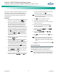
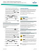
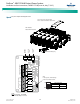
Table Of Contents
- Admonishments Used In This Document
- Important Safety Instructions
- Static Warning
- System Overview
- Installation Acceptance Checklist
- Installing the System
- General Requirements
- Securing the Relay Rack to the Floor
- Mounting System Components in a Relay Rack
- Setting Switch Options
- Making Electrical Connections
- Important Safety Instructions
- Wiring Considerations
- Relay Rack Grounding Connection (Frame Ground)
- AC Input and AC Input Equipment Grounding Connections to Rectifier Module Mounting Shelves
- External Alarm, Reference, Monitoring, and Control Connections
- ACU+ Controller Ethernet Connection (if required)
- -48V DC Output Connections
- Installing the Rectifier Modules and Initially Starting the System
- Installing the Rectifier Modules into Spec. No. 588705000 Rectifier Module Mounting Shelves
- Initially Starting, Configuring, and Checking System Operation
- Important Safety Instructions
- Initial Startup Preparation
- Initially Starting the System
- ACU+ Controller Initialization
- Verifying the Configuration File
- Checking Basic System Settings
- Changing Battery Capacity Rating in the ACU+
- Configuring the ACU+ Identification of Rectifiers and Assigning which Input Phase is Connected to the Rectifiers
- ACU+ Alarm Relay Check
- Checking System Status
- Final Steps
- Operating Procedures
- Maintenance
- Troubleshooting and Repair
- NetPerform™ Optimization Services
NetSure
™
-48V DC Bulk Output Power System
Installation and User Instructions, UM582127100 (Issue AA, May 7, 2013)
Spec. No: 582127100 UM582127100
Model No: 722NBBB Issue AA, May 7, 2013
38
PROCEDURE
1. Performing this procedure may activate external alarms.
Do one of the following. If possible, disable these alarms.
If these alarms cannot be easily disabled, notify the
appropriate personnel to disregard any future alarms
associated with this system while the procedure is being
performed.
Warning! Damage to the circuit card may result if the
next step is not followed.
2. Connect an approved grounding strap to your wrist.
Attach the other end to a suitable ground.
3. Loosen the captive fastener that secures the IB2 (ACU+
Interface Board) sliding tray to the main rectifier module
mounting shelf. Carefully slide the assembly out until the
wires are accessible. Refer to Figure 18. Note that the
top cover can be removed from the ACU+ section to
facilitate IB2 replacement.
4. Remove the shield covering the IB2 (ACU+ Interface
Board). The shield is secured with two (2) of the circuit
card’s mounting screws.
5. Carefully label the wires connected to the customer
connection terminal blocks J3 through J9 on the circuit
card. These wires must be connected to the same
terminals on the replacement circuit card. Refer to
Figure 18.
6. Carefully label the connectors plugged into the circuit
card. These connectors must be plugged into the same
connectors on the replacement circuit card. Refer to
Figure 18.
Danger! In the next step, external wiring may be
energized from an external source. DO NOT allow bare
wire ends to contact any grounded or energized object.
7. Remove the external wiring from the customer
connection terminal blocks. DO NOT allow the bare wire
end to contact any grounded or energized object. Isolate
the wire end with electrical tape. Repeat for each wire to
be removed.
8. Unplug all connectors plugged into the circuit card.
9. Remove the remaining circuit card mounting screws and
remove the circuit card from the mounting plate.
10. In this step, ensure you do not intermix the old and
replacement circuit cards. Set the switch on the
replacement circuit card to the same setting as the old
circuit card. Refer to Figure 18.
11. Orient the replacement IB2 circuit card over its mounting
position. Replace the shield over the circuit card and
secure the circuit card to the mounting plate.
12. Carefully slide the IB2 (ACU+ Interface Board) assembly
partially into the main rectifier module mounting shelf.
13. Plug all connectors removed from the old circuit card into
the same position on the replacement circuit card.
Danger! In the next step, external alarm wiring may be
energized from an external source. DO NOT allow bare
wire ends to contact any grounded or energized object.
14. Reconnect the external wiring to the correct terminals on
the customer connection terminal blocks. First remove
the electrical tape that was applied to the bare wire end
in a previous step. DO NOT allow the bare wire end to
contact any grounded or energized object. After
securing the wire, gently tug on the wire to ensure that it
cannot be pulled out of the terminal block. Repeat for
each wire to be reconnected.
15. Slide the IB2 (ACU+ Interface Board) assembly
completely into the main rectifier module mounting shelf
and secure with the captive fastener.
16. Remove the grounding wrist strap.
17. Enable the external alarms, or notify appropriate
personnel that this procedure is finished.
18. Ensure that there are no local or remote alarms active on
the system.