
Brochures and Data Sheets
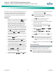
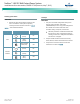
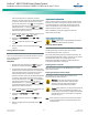
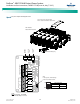
Table Of Contents
- Admonishments Used In This Document
- Important Safety Instructions
- Static Warning
- System Overview
- Installation Acceptance Checklist
- Installing the System
- General Requirements
- Securing the Relay Rack to the Floor
- Mounting System Components in a Relay Rack
- Setting Switch Options
- Making Electrical Connections
- Important Safety Instructions
- Wiring Considerations
- Relay Rack Grounding Connection (Frame Ground)
- AC Input and AC Input Equipment Grounding Connections to Rectifier Module Mounting Shelves
- External Alarm, Reference, Monitoring, and Control Connections
- ACU+ Controller Ethernet Connection (if required)
- -48V DC Output Connections
- Installing the Rectifier Modules and Initially Starting the System
- Installing the Rectifier Modules into Spec. No. 588705000 Rectifier Module Mounting Shelves
- Initially Starting, Configuring, and Checking System Operation
- Important Safety Instructions
- Initial Startup Preparation
- Initially Starting the System
- ACU+ Controller Initialization
- Verifying the Configuration File
- Checking Basic System Settings
- Changing Battery Capacity Rating in the ACU+
- Configuring the ACU+ Identification of Rectifiers and Assigning which Input Phase is Connected to the Rectifiers
- ACU+ Alarm Relay Check
- Checking System Status
- Final Steps
- Operating Procedures
- Maintenance
- Troubleshooting and Repair
- NetPerform™ Optimization Services

NetSure
™
-48V DC Bulk Output Power System
Installation and User Instructions, UM582127100 (Issue AA, May 7, 2013)
Spec. No: 582127100 UM582127100
Model No: 722NBBB Issue AA, May 7, 2013
37
step and proceed to step 3. Otherwise, to enter a
password, with the cursor at the User Name field (default
is “Admin”), press the down arrow key to move cursor
down to the password line. Press ENT. “0” is highlighted.
Press the up arrow key once to change the “0” to”1”
(default password is “1”), then press ENT twice. (Note: If
you have been assigned a unique User Name and password,
follow this procedure to enter these.)
3. With the Manual menu screen displayed, navigate to and
select “Rectifier” (ENT) / “All Rect Ctrl” (ENT).
4. Navigate to “Clear Comm Fail”. Press ENT. “Yes”
highlights.
5. Press ENT to select the operation. Press ENT again to
confirm.
6. Return to the Main screen by repeatedly pressing ESC
(escape).
Clearing a Rectifier Lost Alarm
If the ACU+ Controller resets while a rectifier communications fail
alarm is active, the rectifier communications fail alarm is replace
with a rectifier lost alarm. To clear the alarm, perform the
following procedure.
PROCEDURE
1. With the Main screen displayed, press ENT to go to the
Main Menu. Navigate to and select “Manual” (ENT).
2. If a password screen opens, a password must be entered
to allow the User to make adjustments. If a password was
previously entered and has not yet timed out, skip this
step and proceed to step 3. Otherwise, to enter a
password, with the cursor at the User Name field (default
is “Admin”), press the down arrow key to move cursor
down to the password line. Press ENT. “0” is highlighted.
Press the up arrow key once to change the “0” to”1”
(default password is “1”), then press ENT twice. (Note: If
you have been assigned a unique User Name and password,
follow this procedure to enter these.)
3. With the Manual menu screen displayed, navigate to and
select “Rectifier” (ENT) / “All Rect Ctrl” (ENT).
4. Navigate to “Clear Rect Lost”. Press ENT. “Clear”
highlights.
5. Press ENT to select the operation. Press ENT again to
confirm.
6. Return to the Main screen by repeatedly pressing ESC
(escape).
Replacement Information
When a trouble symptom is localized to a faulty rectifier module,
controller, or system circuit card; that particular device or circuit
card should be replaced in its entirety. No attempt should be
made to troubleshoot or repair individual components on any
rectifier module, controller, or circuit card.
Refer to SAG582127100 (System Application Guide) for
replacement part numbers.
Replacement Procedures
Danger! Adhere to the “Important Safety Instructions”
presented at the front of this document.
Replacing a Rectifier Module
Refer to the Rectifier Instructions (UM1R483500E) for a rectifier
module replacement procedure. Refer also to “System
Troubleshooting Information” on page 36.
The rectifier module being replaced is assigned by the ACU+ the
lowest available identification number. If desired, you can change
the identification number, see “Configuring the ACU+
Identification of Rectifiers and Assigning which Input Phase is
Connected to the Rectifiers” on page 32.
Replacing the ACU+ Controller
Refer to the ACU+ Instructions (UM1M820BNA) for a controller
replacement procedure.
Replacing the IB2 (ACU+ Interface Board)
The following circuit card replacement procedure can be
performed with the system operating.
Warning! Circuit cards used in this power system
contain static-sensitive devices. Read the Static
Warning at the front of this document before
performing any of the following procedures.
Caution! When performing any step in these procedures
that requires removal or installation of hardware, use
caution to ensure no hardware is dropped and left inside
the shelf; otherwise service interruption or equipment
damage may occur.
Note: When performing any step in these procedures that requires
removal of existing hardware, retain all hardware for use in
subsequent steps.