
Brochures and Data Sheets
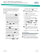
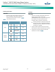
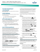
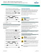
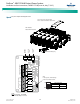
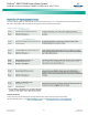
Table Of Contents
- Admonishments Used In This Document
- Important Safety Instructions
- Static Warning
- System Overview
- Installation Acceptance Checklist
- Installing the System
- General Requirements
- Securing the Relay Rack to the Floor
- Mounting System Components in a Relay Rack
- Setting Switch Options
- Making Electrical Connections
- Important Safety Instructions
- Wiring Considerations
- Relay Rack Grounding Connection (Frame Ground)
- AC Input and AC Input Equipment Grounding Connections to Rectifier Module Mounting Shelves
- External Alarm, Reference, Monitoring, and Control Connections
- ACU+ Controller Ethernet Connection (if required)
- -48V DC Output Connections
- Installing the Rectifier Modules and Initially Starting the System
- Installing the Rectifier Modules into Spec. No. 588705000 Rectifier Module Mounting Shelves
- Initially Starting, Configuring, and Checking System Operation
- Important Safety Instructions
- Initial Startup Preparation
- Initially Starting the System
- ACU+ Controller Initialization
- Verifying the Configuration File
- Checking Basic System Settings
- Changing Battery Capacity Rating in the ACU+
- Configuring the ACU+ Identification of Rectifiers and Assigning which Input Phase is Connected to the Rectifiers
- ACU+ Alarm Relay Check
- Checking System Status
- Final Steps
- Operating Procedures
- Maintenance
- Troubleshooting and Repair
- NetPerform™ Optimization Services
NetSure
™
-48V DC Bulk Output Power System
Installation and User Instructions, UM582127100 (Issue AA, May 7, 2013)
Spec. No: 582127100 UM582127100
Model No: 722NBBB Issue AA, May 7, 2013
35
Operating Procedures
Controller and Rectifiers
For operation instructions on these units, refer to the following
documents.
ACU+ Controller Instructions (UM1M820BNA)
Rectifier Instructions (UM1R483500E)
ESTOP Function
If an ESTOP switch is wired to the ACU+ IB2 Interface Board,
customer-furnished system ground applied to terminal DI8+
activates the ESTOP function. The ESTOP function shuts down and
locks out the rectifiers. To restart the rectifiers after removing the
ESTOP signal; turn AC power to the rectifiers OFF, wait 30 seconds
or more (until the LEDs on the rectifier extinguish), then turn AC
power to the rectifiers ON. Rectifiers can also be restarted from
the ACU+ LCD or WEB Interface menu (via the Rectifier Reset
command, found in the Manual menu in the LCD menus or under
the Rectifier Control Tab in the WEB Interface).
ACU+ Battery Charge Current Limit Feature
Functionality: After a commercial AC failure or when some battery
cells are permanently damaged, the current to the batteries can be
quite extensive. To avoid overheating or further damages to the
battery, the ACU+ can be programmed to limit the battery current
to a preset level by limiting the charging voltage of the rectifiers.
Should the battery current still exceed a higher preset value, an
alarm is issued.
In this system, the ACU+ Battery Charge Current Limit feature is set
to be enabled. If enabled, battery charge current is limited to the
value set in the ACU+ Controller, as long as battery voltage is
above 47VDC. Refer to the ACU+ Controller Instructions
(UM1M820BNA) for more information.
Local Controls and Indicators
Refer to the Controller and Rectifier Instructions for descriptions of
the local controls and indicators located on these units.
Maintenance
System Maintenance Procedures
It is recommended to perform the maintenance procedures listed
in Table 9 every 6-months to ensure continual system operation.
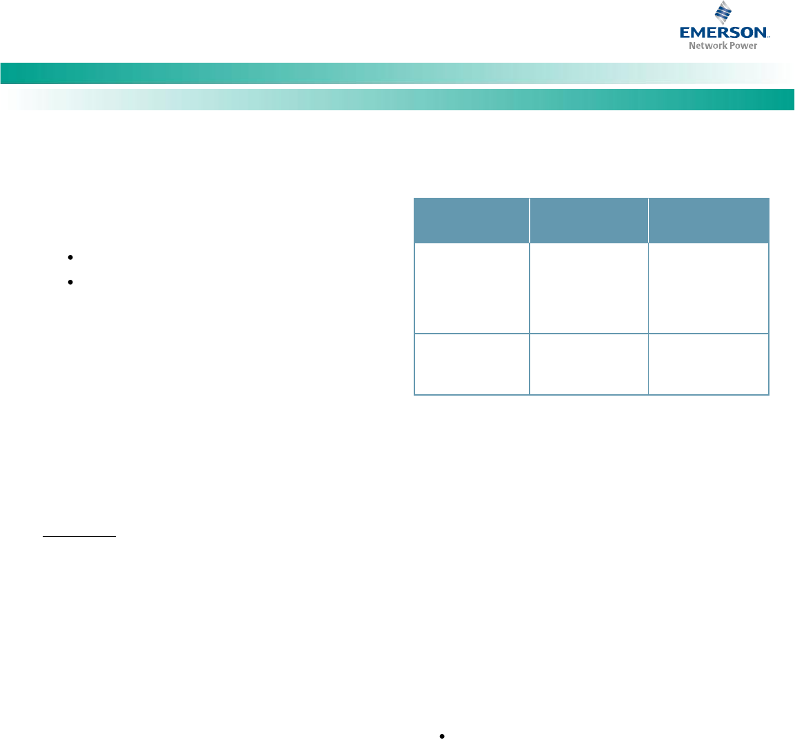
Table 9. Maintenance Procedures to be Performed at 6-Month
Intervals
PROCEDURE
REFERENCED IN
COMPLETED (√)
Check ventilation
openings for
obstructions such
as dust, papers,
manuals, etc.
--
Inspect and tighten
all installer's
connections.
“Making Electrical
Connections”
starting on page11.
Note: This table may be reproduced as necessary to record and
document system performance.
Adding a Rectifier Module to an Existing Rectifier
Module Mounting Shelf Spec. No. 588705000
To increase system current capacity, a rectifier module can easily
be added to an existing rectifier module mounting shelf Spec. No.
588705000 that contains an empty rectifier module mounting
position.
It is recommended that the current limit point be checked
whenever a rectifier module is added to or removed from the
power system. Refer to “Checking the ACU+ Current Limit Point
after Adding or Removing a Rectifier” on page 36.
The rectifier module being added is assigned by the ACU+ the
lowest available identification number. If desired, you can change
the identification number, see “Configuring the ACU+
Identification of Rectifiers and Assigning which Input Phase is
Connected to the Rectifiers” on page 32.
For rectifier module installation instructions, refer to
“Installing the Rectifier Modules into Spec. No.
588705000 Rectifier Module Mounting Shelves” on page
29.
Installing a Field Expansion Rectifier Module
Mounting Shelf Spec. No. 588705000
Refer to “Mounting System Components in a Relay Rack” on page
2.