
Brochures and Data Sheets
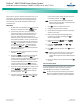
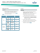
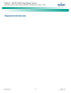
Table Of Contents
- Admonishments Used In This Document
- Important Safety Instructions
- Static Warning
- System Overview
- Installation Acceptance Checklist
- Installing the System
- General Requirements
- Securing the Relay Rack to the Floor
- Mounting System Components in a Relay Rack
- Setting Switch Options
- Making Electrical Connections
- Important Safety Instructions
- Wiring Considerations
- Relay Rack Grounding Connection (Frame Ground)
- AC Input and AC Input Equipment Grounding Connections to Rectifier Module Mounting Shelves
- External Alarm, Reference, Monitoring, and Control Connections
- ACU+ Controller Ethernet Connection (if required)
- -48V DC Output Connections
- Installing the Rectifier Modules and Initially Starting the System
- Installing the Rectifier Modules into Spec. No. 588705000 Rectifier Module Mounting Shelves
- Initially Starting, Configuring, and Checking System Operation
- Important Safety Instructions
- Initial Startup Preparation
- Initially Starting the System
- ACU+ Controller Initialization
- Verifying the Configuration File
- Checking Basic System Settings
- Changing Battery Capacity Rating in the ACU+
- Configuring the ACU+ Identification of Rectifiers and Assigning which Input Phase is Connected to the Rectifiers
- ACU+ Alarm Relay Check
- Checking System Status
- Final Steps
- Operating Procedures
- Maintenance
- Troubleshooting and Repair
- NetPerform™ Optimization Services
NetSure
™
-48V DC Bulk Output Power System
Installation and User Instructions, UM582127100 (Issue AA, May 7, 2013)
Spec. No: 582127100 UM582127100
Model No: 722NBBB Issue AA, May 7, 2013
34
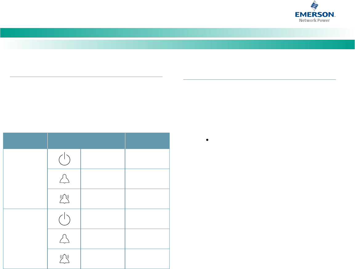
Checking System Status
PROCEDURE
1. Observe the status of the indicators located on the
ACU+ and rectifiers. If the system is operating
normally, the status of these is as shown in Table 8.
Table 8. Status and Alarm Indicators
Component
Indicator
Normal State
ACU+
Status
(Green)
On
Minor
(Yellow)
Off
Critical or Major
Alarm (Red)
Off
Rectifier
Modules
Power
(Green)
On
Protection
(Yellow)
Off
Alarm
(Red)
Off
Final Steps
PROCEDURE
1. If any ACU+ Controller configuration settings were
changed, refer to the ACU+ Instructions
(UM1M820BNA) and save a copy of the configuration
file. This file can be used to restore the ACU+
Controller settings, if required, at a later date.
Note that provided on a USB drive furnished with
the system is an ACU+ configuration drawing (C-
drawing) and the ACU+ configuration files loaded
into the ACU+ as shipped.
2. Verify all rectifier modules and the ACU+ are fully
seated, latched, and the latch handle screws secured.
3. Verify there are no external alarms and the local
indicators are as shown in Table 8.