
Brochures and Data Sheets

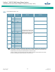

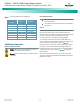

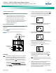
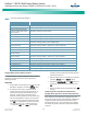
Table Of Contents
- Admonishments Used In This Document
- Important Safety Instructions
- Static Warning
- System Overview
- Installation Acceptance Checklist
- Installing the System
- General Requirements
- Securing the Relay Rack to the Floor
- Mounting System Components in a Relay Rack
- Setting Switch Options
- Making Electrical Connections
- Important Safety Instructions
- Wiring Considerations
- Relay Rack Grounding Connection (Frame Ground)
- AC Input and AC Input Equipment Grounding Connections to Rectifier Module Mounting Shelves
- External Alarm, Reference, Monitoring, and Control Connections
- ACU+ Controller Ethernet Connection (if required)
- -48V DC Output Connections
- Installing the Rectifier Modules and Initially Starting the System
- Installing the Rectifier Modules into Spec. No. 588705000 Rectifier Module Mounting Shelves
- Initially Starting, Configuring, and Checking System Operation
- Important Safety Instructions
- Initial Startup Preparation
- Initially Starting the System
- ACU+ Controller Initialization
- Verifying the Configuration File
- Checking Basic System Settings
- Changing Battery Capacity Rating in the ACU+
- Configuring the ACU+ Identification of Rectifiers and Assigning which Input Phase is Connected to the Rectifiers
- ACU+ Alarm Relay Check
- Checking System Status
- Final Steps
- Operating Procedures
- Maintenance
- Troubleshooting and Repair
- NetPerform™ Optimization Services

NetSure
™
-48V DC Bulk Output Power System
Installation and User Instructions, UM582127100 (Issue AA, May 7, 2013)
Spec. No: 582127100 UM582127100
Model No: 722NBBB Issue AA, May 7, 2013
32
Table 7. ACU+ Basic Settings Menu Navigation
Parameter
Menu Navigation
Date
Main Menu / Settings / Controller / Date
Time
Main Menu / Settings / Controller / Time
IP Communications Parameters
(IP address, subnet mask address,
gateway address)
Main Menu / Settings / Communication
Float Voltage
Main Menu / Settings / Battery / Charge / Float Voltage
Equalize Voltage
Main Menu / Settings / Battery / Charge / EQ Voltage
Battery Capacity
Main Menu / Settings / Battery / Battery 1 / Rated Capacity
BTRM Feature
Main Menu / Settings / Battery / Basic / BTRM Action
Main Menu / Settings / Battery / Basic / BTRM Voltage
Temperature Compensation
Center Temperature
Main Menu / Settings / Battery / Temp Comp / Temp CompCenter
Temperature Compensation Slope
Main Menu / Settings / Battery / Temp Comp / Temp Comp Coeff
Temperature Compensation Sensor
Main Menu / Settings / Battery / Temp Comp / TempComp Sensor
Temperature Compensation
Maximum Voltage
Main Menu / Settings / Battery / Temp Comp / Temp Comp Max V
Temperature Compensation
Minimum Voltage
Main Menu / Settings / Battery / Temp Comp / Temp Comp Min V
HVSD Limit
Main Menu / Settings / Rectifier / All Rect Set / HVSD Limit
Rectifier Current Limit
Main Menu / Settings / Rectifier / All Rect Set / Curr Limit Pt
Over Voltage Alarm 1
Main Menu / Settings / Power System / General / Over Voltage 1
Over Voltage Alarm 2
Main Menu / Settings / Power System / General / Over Voltage 2
Under Voltage Alarm 1
Main Menu / Settings / Power System / General / Under Voltage 1
Under Voltage Alarm 2
Main Menu / Settings / Power System / General / Under Voltage 2
Changing Battery Capacity Rating in the ACU+
To change the battery capacity setting of the ACU+ to match
the battery connected to the power system, perform the
following procedure.
PROCEDURE
1. With the Main screen displayed, press ENT to go to the
Main Menu. Navigate to and select “Settings” (ENT).
2. If a password screen opens, a password must be
entered to allow the User to make adjustments. If a
password was previously entered and has not yet
timed out, skip this step and proceed to step 3).
Otherwise, to enter a password, with the cursor at the
User Name field (default is “Admin”), press the down
arrow key to move cursor down to the password line.
Press ENT. “0” is highlighted. Press the up arrow key
once to change the “0” to”1” (default password is
“1”), then press ENT twice. (Note: If you have been
assigned a unique User Name and password, follow this
procedure to enter these.)
3. With the Settings menu screen displayed, navigate to
and select “Battery” (ENT) / “Battery 1” (ENT).
4. Navigate to “Rated Capacity”. Press ENT. Use the up
or down keys to adjust the value as required. Press
ENT.
5. Return to the Main screen by repeatedly pressing ESC
(escape).
Configuring the ACU+ Identification of Rectifiers and
Assigning which Input Phase is Connected to the Rectifiers
When rectifiers are all installed prior to applying power and
starting the system, the order in which the ACU+ identifies the
rectifiers is by serial number (lowest serial number is Rect 1,
next lowest is Rect 2, etc.). If you prefer the ACU+ to identify
the rectifiers by position in the system, perform the following
procedure.