
Brochures and Data Sheets

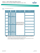

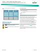

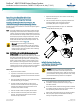
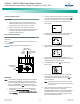
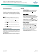
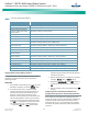
Table Of Contents
- Admonishments Used In This Document
- Important Safety Instructions
- Static Warning
- System Overview
- Installation Acceptance Checklist
- Installing the System
- General Requirements
- Securing the Relay Rack to the Floor
- Mounting System Components in a Relay Rack
- Setting Switch Options
- Making Electrical Connections
- Important Safety Instructions
- Wiring Considerations
- Relay Rack Grounding Connection (Frame Ground)
- AC Input and AC Input Equipment Grounding Connections to Rectifier Module Mounting Shelves
- External Alarm, Reference, Monitoring, and Control Connections
- ACU+ Controller Ethernet Connection (if required)
- -48V DC Output Connections
- Installing the Rectifier Modules and Initially Starting the System
- Installing the Rectifier Modules into Spec. No. 588705000 Rectifier Module Mounting Shelves
- Initially Starting, Configuring, and Checking System Operation
- Important Safety Instructions
- Initial Startup Preparation
- Initially Starting the System
- ACU+ Controller Initialization
- Verifying the Configuration File
- Checking Basic System Settings
- Changing Battery Capacity Rating in the ACU+
- Configuring the ACU+ Identification of Rectifiers and Assigning which Input Phase is Connected to the Rectifiers
- ACU+ Alarm Relay Check
- Checking System Status
- Final Steps
- Operating Procedures
- Maintenance
- Troubleshooting and Repair
- NetPerform™ Optimization Services
NetSure
™
-48V DC Bulk Output Power System
Installation and User Instructions, UM582127100 (Issue AA, May 7, 2013)
Spec. No: 582127100 UM582127100
Model No: 722NBBB Issue AA, May 7, 2013
30
Initially Starting the System
PROCEDURE
1. Apply DC input power to the system by closing the
external DC disconnect(s) or protective device(s) that
supplies battery power to the system, if furnished.
2. Apply AC input power to the system by closing ALL
external AC disconnects or protective devices that supply
AC power to the rectifier module mounting shelves.
Rectifiers automatically start.
ACU+ Controller Initialization
Refer to the ACU+ Instructions (UM1M820BNA) for detailed
instructions.
Refer to Figure 17 for locations of the ACU+ local indicators and
navigation keys.
Figure 17. ACU+ Local Indicators and Navigation Keys
PROCEDURE
Note: The initialization routine takes several minutes. During that
time various alarm indicators may illuminate on the ACU+
front panel and an audible alarm may sound. Disregard all
alarms. An audible alarm can be silenced at any time by
momentarily depressing the ENT key on the ACU+ Controller.
1. After the ACU+ is powered on, the display alternates
between the “Emerson Network Power” screen and a
screen displaying “Advanced Control Unit Plus Version
***** Starting….
2. Next, the language screen appears. Press the up or down
arrow key to select the desired language. Press the ENT
key to confirm the selection. If no key is pressed within
10 seconds, the ACU+ selects the displayed language
automatically.
3. As initialization continues, the Main screen is displayed,
but with zero volts. Initialization is not complete.
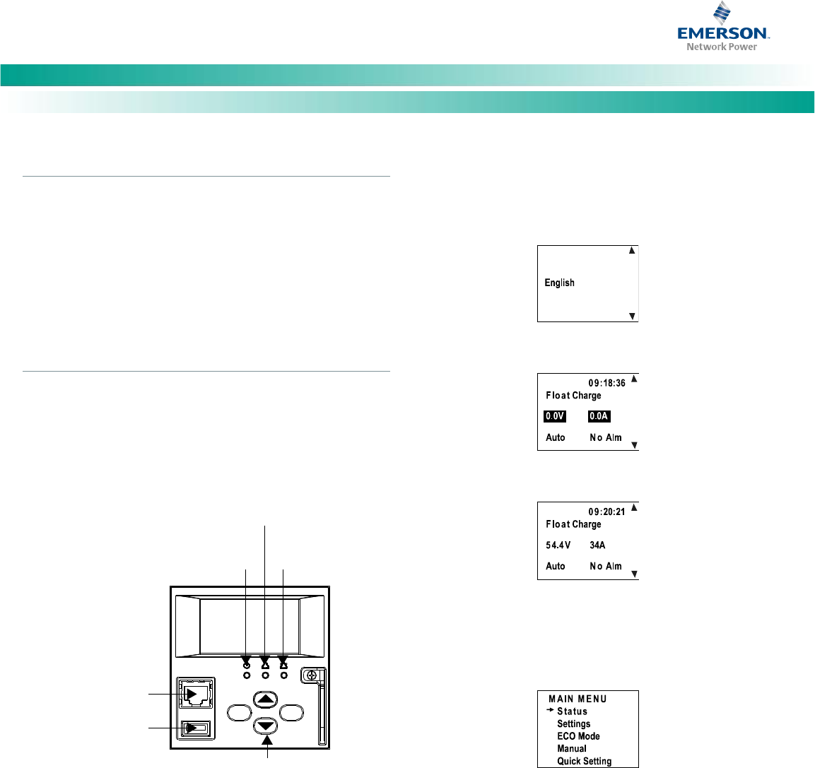
4. When initialization is complete, the Main screen displays
voltage and current normally, and no alarms are active.
5. System information is displayed in multiple screens.
Repetitively press the up or down arrow key to view other
system information screens one by one.
6. From the Main screen, press ENT to go to the “Main
Menu” screen.
7. From the Main Menu, select a submenu by repetitively
pressing the up or down arrow key. The selected
submenu will be indicated by the cursor. Press ENT to
open the submenu.
Note: Repeatedly press the “ESC” key to return in reverse
order level by level from any submenu until the Main
screen appears.
8. Verify and set the ACU+ controller as required for your
application. Refer to the ACU+ Instructions
(UM1M820BNA) for procedures. Note that you will have
to program the ACU+ for any temperature probes and
external inputs/outputs connected to the IB2 Interface
Board and System Interface Board.
Status
Indicator
(Green)
Minor Alarm
Indicator (Yellow)
Critical or Major
Alarm Indicator
(Red)
ESC ENT
Menu Navigation Keys
USB
Port
10/100M Ethernet
Port (RJ-45)