
Brochures and Data Sheets

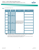

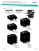

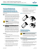
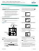
Table Of Contents
- Admonishments Used In This Document
- Important Safety Instructions
- Static Warning
- System Overview
- Installation Acceptance Checklist
- Installing the System
- General Requirements
- Securing the Relay Rack to the Floor
- Mounting System Components in a Relay Rack
- Setting Switch Options
- Making Electrical Connections
- Important Safety Instructions
- Wiring Considerations
- Relay Rack Grounding Connection (Frame Ground)
- AC Input and AC Input Equipment Grounding Connections to Rectifier Module Mounting Shelves
- External Alarm, Reference, Monitoring, and Control Connections
- ACU+ Controller Ethernet Connection (if required)
- -48V DC Output Connections
- Installing the Rectifier Modules and Initially Starting the System
- Installing the Rectifier Modules into Spec. No. 588705000 Rectifier Module Mounting Shelves
- Initially Starting, Configuring, and Checking System Operation
- Important Safety Instructions
- Initial Startup Preparation
- Initially Starting the System
- ACU+ Controller Initialization
- Verifying the Configuration File
- Checking Basic System Settings
- Changing Battery Capacity Rating in the ACU+
- Configuring the ACU+ Identification of Rectifiers and Assigning which Input Phase is Connected to the Rectifiers
- ACU+ Alarm Relay Check
- Checking System Status
- Final Steps
- Operating Procedures
- Maintenance
- Troubleshooting and Repair
- NetPerform™ Optimization Services
NetSure
™
-48V DC Bulk Output Power System
Installation and User Instructions, UM582127100 (Issue AA, May 7, 2013)
Spec. No: 582127100 UM582127100
Model No: 722NBBB Issue AA, May 7, 2013
29
Installing the Rectifier Modules
and Initially Starting the System
Installing the Rectifier Modules into Spec. No.
588705000 Rectifier Module Mounting Shelves
Rectifier modules can be inserted or removed with power applied
(hot swappable).
Note: The rectifier module locks into the rectifier module mounting
shelf through a latch located on the underside of the rectifier
module. The latch and rectifier module handle are interactive.
Push the handle into the rectifier module’s front panel, and the
latch will pop out from the rectifier module bottom. Click the
handle to pop it out from the rectifier module’s front panel,
and the latch will retract back into the rectifier module. The
latch mechanism is shown in Figure 16.
Warning! To prevent damage to the latching
mechanism, ensure the handle is in the open position
when installing or removing a rectifier module. NEVER
hold the handle in the closed position when installing a
rectifier module into a shelf.
Note: 588705000 List 52 and 62 Rectifier Mounting Shelves Only
(3-Phase Input): One three-phase input feeds the three
rectifier modules on the left-hand side of the shelf. The second
three-phase input feeds the two (List 62) or three (List 52)
rectifier modules on the right-hand side. To maintain phase
balance, install rectifier modules in groups of three (List 52);
that is, fill all three mounting positions on the left and/or all
three on the right. To maintain phase balance, install rectifier
modules in groups of two or three (List 62); that is, fill all three
mounting positions on the left and/or all two on the right.
PROCEDURE
1. Unpack the rectifier modules.
2. If present, remove blank cover panels from the rectifier
module mounting positions into which rectifier modules
are to be installed.
3. Place the rectifier module into an unoccupied mounting
slot without sliding it in completely.
4. Click the rectifier module handle in order to pop it
forwards out of the rectifier module’s front panel (this
will also retract the latch mechanism located on the
underside of the rectifier module).
5. Push the rectifier module completely into the shelf.
6. Push the handle into the front panel of the rectifier
module. This will make the latch lock the rectifier
module securely to the shelf.
7. Repeat the above steps for each rectifier module being
installed in the system.
8. After the rectifier modules are physically installed in the
mounting shelf(s), they are ready for operation
immediately after power is supplied to them.
Figure 16. Installing Rectifier Modules into Spec. No. 588705000
Rectifier Module Mounting Shelf
Initially Starting, Configuring,
and Checking System Operation
Important Safety Instructions
Caution! Performing various steps in the following
procedures may cause a service interruption and/or
result in the extension of alarms. Notify any appropriate
personnel before starting these procedures. Also, notify
personnel when these procedures are completed.
Initial Startup Preparation
Ensure that all blocks, except the last one, in the
“Installation Acceptance Checklist” starting on page 1
have been checked.
Ensure that rectifier module mounting positions are filled
by a rectifier module or a blank cover panel as desired. It
is acceptable for positions to be left vacant.
Refer to the configuration drawing (C-drawing) supplied
with your power system documentation for factory
settings of adjustable parameters.