
Brochures and Data Sheets

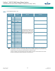

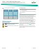
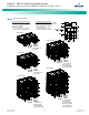

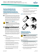
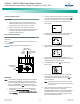
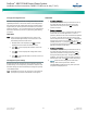
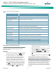
Table Of Contents
- Admonishments Used In This Document
- Important Safety Instructions
- Static Warning
- System Overview
- Installation Acceptance Checklist
- Installing the System
- General Requirements
- Securing the Relay Rack to the Floor
- Mounting System Components in a Relay Rack
- Setting Switch Options
- Making Electrical Connections
- Important Safety Instructions
- Wiring Considerations
- Relay Rack Grounding Connection (Frame Ground)
- AC Input and AC Input Equipment Grounding Connections to Rectifier Module Mounting Shelves
- External Alarm, Reference, Monitoring, and Control Connections
- ACU+ Controller Ethernet Connection (if required)
- -48V DC Output Connections
- Installing the Rectifier Modules and Initially Starting the System
- Installing the Rectifier Modules into Spec. No. 588705000 Rectifier Module Mounting Shelves
- Initially Starting, Configuring, and Checking System Operation
- Important Safety Instructions
- Initial Startup Preparation
- Initially Starting the System
- ACU+ Controller Initialization
- Verifying the Configuration File
- Checking Basic System Settings
- Changing Battery Capacity Rating in the ACU+
- Configuring the ACU+ Identification of Rectifiers and Assigning which Input Phase is Connected to the Rectifiers
- ACU+ Alarm Relay Check
- Checking System Status
- Final Steps
- Operating Procedures
- Maintenance
- Troubleshooting and Repair
- NetPerform™ Optimization Services
NetSure
™
-48V DC Bulk Output Power System
Installation and User Instructions, UM582127100 (Issue AA, May 7, 2013)
Spec. No: 582127100 UM582127100
Model No: 722NBBB Issue AA, May 7, 2013
27
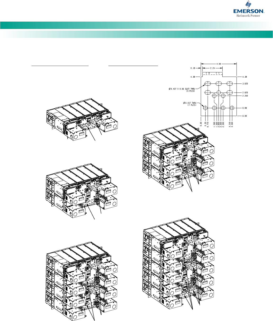
Figure 14. -48V DC Output Connections
GND RTN
Busbars
-48V DC
Output
Busbars
GND RTN
Busbars
-48V DC
Output
Busbars
GND RTN
Busbars
-48V DC
Output
Busbars
GND RTN
Busbars
-48V DC
Output
Busbars
GND RTN
Busbars
-48V DC
Output
Busbars
Rear
Rear
Rear
Rear
Rear
1-Shelf System
2-Shelf System
3-Shelf System
(1) connection per
two shelves.
(1) connection per
two shelves (top).
(1) connection per
two shelves (bottom).
(1) connection per
two shelves (top).
(1) connection per
single shelf (bottom).
(1) connection per
two shelves (top).
(1) connection per
two shelves (middle).
(1) connection per
single shelf (bottom).
(1) connection per
single shelf.
4-Shelf System
5-Shelf System
-48V DC OUTPUT CONNECTIONS
3/8 Clearance Holes on 1” Centers
(Customer must order or supply
lug mounting hardware.)
Maximum Lug Width:
1.31” for three (3) lugs per polarity.
1.78” for two (2) lugs per polarity.
DC Output Connection Options
1. Route cables left, right, or out the back
by repositioning the lug landing busbars.
2. Make connections to each shelf
(List 10 and 11).
3. Make connections to every
two (2) shelves (List 20 and 21).